Dukane P42 user manual Product Specifications, Signal Input, Priority

Page 38

PRODUCT SPECIFICATIONS (continued)

ENGLISH

Signal Input

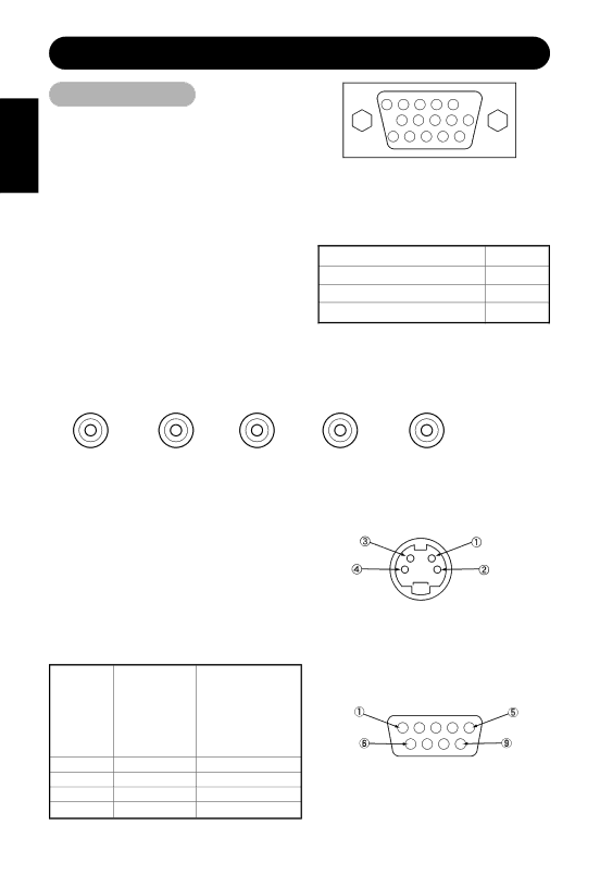
RGB terminal (D-sub 15-pin connector)

Pin

Input signal


1

R. video


2

G. video or sync on green


3

B. video


4

No connection


5

No connection


6

R.GND


7

G.GND


8

B.GND


9

No connection


10

GND


11

No connection


12

[SDA]


13

H. sync or H/V composite sync


14

V.sync. [V.CLK]


15

[SCL]


RGB terminal (BNC connector)

5 4 3 2 1

10 9 8 7 6

15 14 13 12 11

When different kinds of input signals are simultaneously input to the monitor via a graphics board or the like, the monitor will automatically select the signals in the following priority order:

Sync signal type

Priority

H/V separate sync.

1

H/V composite sync.

2

sync.on Green *

3

*Even in the case of the recommended signals shown on the following page, there may be instances when correct display is not possible. In this case, use H/V separate sync, H/V composite sync.

V.sync.

H. sync or H/V

B. video

G. video or sync

R. video


composite sync


on green


S-input connector pin specifications

Pin

Input signal


1

Y


2

Y-GND


3

C


4

C-GND


Frame

GND


Serial connector pin specifications

Pin

Input signal

Remarks

1

No connection


2

RXD

Unit PC


3

TXD

Unit PC


4

No connection


5

GND

Unit GND PC GND

6No connection

7No connection

8No connection

9No connection

28

Image 38
Contents Model P42 Page Do not drop water or a foreign substance on to the monitor Safety GuidelinesIf something smells strange or smoke comes from the monitor Do not put the monitor on an unstable placeSafety Guidelines Do not put the monitor in high temperature atmosphere Do not touch the power plug with wet handsWhen you disconnect the power plug Do not obstruct a ventilation holeDo not coil or wind the power cord Remove the power cord for complete isolationHow to clean the monitor Installation environmentHow to view the monitor Prevention of an obstacle to Radio receivers Precautions for the monitorPrecaution during transportation FCC Federal Communications Commission Statement Warning Page Contents Features Standard AccessoriesAnti-tumble measures Installation InstructionsInstallation Securing to a wall or pillarFront Installation InstructionsComponent Names Control panelMain unit Remote controllerRear Installation and Cabling Connecting to a PCConnecting to Video Equipment External Monitor Video equipmentLoading Batteries Handling the Remote ControllerHandling the Remote Controller Operating Instructions Turning Power On and OffIndicating lamp Power status Operating Input Selection Volume AdjustmentOperating Instructions Sound MuteRGB signal input Contrast AdjustmentInput Signal Status Display Video signal inputPink Menu selection mark Pink when brightness is selectedOn-Screen Display System GuidancePicture Menu Options Menu Sound MenuDisplays According to Selected Display Area RGB input Auto AdjustDisplay Menu RGB Display AreaManual Adjust Menu RGB Display Menu VideoDisplays by Selecting the Display Size Video input Size to ScreenFunction Menu Component Menuvideo Screen Saver MenuDisplay Registration Reproduction Condition Other FeaturesAutomatic Store Display menu item Application Reset Settings InitializationSignal Check Status Display ActionSound Mode OtherfeaturesPower Save Mode Troubleshooting Symptoms That Seemingly Appear to be FailuresVCR FF, REW TroubleshootingIt occurs, switch to composite output or S1 Such as 480i, but it is not a failure. But whenExample AdjustmentActions to Correct Abnormal Displays ABC Product Specifications Panel Dimensions ResolutionPriority Product SpecificationsSignal Input Recommended Signal List RGB signal input RGB1 or RGB2 signal inputComposite / S input Video 1 input Component input Video 1 inputLegal Information Audio Visual Products