Samsung A6 installation manual Fixing the Installation Plate, Then follow Steps

Page 31

INSTALLING THE INDOOR UNIT

Fixing the Installation Plate

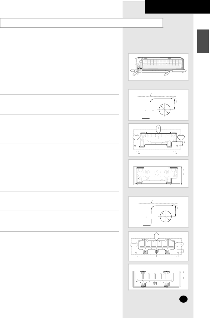
Before fixing the installation plate to a wall or window frame, you must determine the position of the 65mm( 2 169 inch) hole through which the cable, piping and hose pass to connect the indoor unit up to the outdoor unit. When facing the air conditioner in position on the wall, the piping and cable can be connected from the:

Right

Left

Rear (right or left)

1 Determine the position of the pipe and drain hose hole using the right

figure and drill the hole with an inner diameter of 65mm( 2 169 inch) so that it slants slightly downwards.

2

If you are fixing the indoor unit to a...

Then follow Steps...


Wall

3.


Window frame

4 to 6.

3Fix the installation plate to the wall in a manner appropriate to the weight of the indoor unit.

If you are mounting the plate on a concrete wall with anchor bolts, the anchor bolts must not project by more than 20mm( 34 inch).

4Determine the positions of the wooden uprights to be attached to the window frame.

5Attach the wooden uprights to the window frame in a manner appropriate to the weight of the indoor unit.

6Using tapped screws, attach the installation plate to the wooden uprights, as illustrated in the last figure opposite.

ENGLISH

✴✴07/09/12✴✴


Unit : mm(inch) Installation plate


)


3 16

Pipe Hole

30mm(1

065mm (2 9

)

16


Unit : mm(inch)

)


3 8


(2


60


252 (10)


275 (11)


)


3 16


(1


30

90 (3 5 )

140 (5

1 )

8


2

Unit : mm(inch)


)


3 4


~28


1 8


(16


410~730

✴✴18/24✴✴


Unit : mm(inch)

Installation plate


)


3 4

Pipe Hole

45mm/(1

065mm (2 9

)


16


Unit : mm(inch)

)


3 8


(2


60


255 (10)


325 (12 43

)


)


3 4


(1


45

512 (20)

415 (16

3

)


8


Unit : mm(inch)

)

3 4

~ 28

1 8

410~730(16

E-31

Image 31
Contents Installation Manual Manual DE Instrucciones Safety Precautions Contents Indoor Unit View of the UnitOutdoor Unit Remote Control Buttons and Display Getting Started Inserting the Remote Control Batteries To obtain an Using with the indoor unitSelecting with the Remote Control Way FunctionSelecting the Automatic Operating Mode Cooling Your Room Changing the Room Temperature Quickly Removing Excess Humidity Airing Your Room Adjusting the Air Flow Direction Horizontally Adjusting the Air Flow Direction VerticallyTo Cancel the On Timer Setting the On TimerTo Cancel the Off Timer Setting the Off TimerTo Cancel the Sleep Timer Setting the Sleep TimerTopic Recommendation Operating RecommendationsMode Outdoor Temperature Indoor Temperature Indoor Humidity Temperature and Humidity RangesIf the air conditioner is used at... Then Model AS07A5A6MA / AS09A5A6MA / AS12A5A6MC Cleaning Your Air ConditionerAUTO, Cool Solving Common ProblemsInstalling a Filter Option Model Technical SpecificationsOutdoor Unit Installation Manual Electrical Work Indoor Unit Deciding on Where to Install the Air Conditioner30mm1inch or more Accessories in the Indoor Unit Case Air Conditioner and AccessoriesAccessories in the Outdoor Unit Case Then follow Steps Fixing the Installation PlatePurging the Unit Connecting the Assembly Cable07/09/12 To install the drain hose, proceed as follows Installing and Connecting the Indoor Unit Drain HosePipe Installing and Connecting the Indoor Unit Assembly PipingTorque Depth a Cutting/Extending the Piping07/09 Connecting the Cables to the Outdoor Unit18/24 Electrical Work Auxiliary Circuit Breaker5019 Checking Correct EarthingFixing the Unit in Position If you have used Then Connecting Up and Purging the CircuitPerforming Leak Tests To check for gas leaks on Then, using a leak detector CheckPlacing the Indoor Unit in Position Checking and Testing Operations Explaining Operations to the Owner Electronics