Samsung A6 installation manual Checking Correct Earthing, 5019

Page 39

Checking Correct Earthing

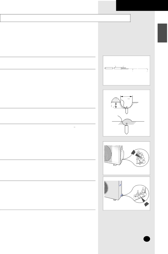
If the power distribution circuit does not have an earth or the earth does not comply with specifications, an earthing electrode must be installed. The corresponding accessories are not supplied with the air conditioner.

1Select an earthing electrode that complies with the specifications given in the illustration opposite.

2Determine a suitable location for the earthing electrode:

In damp hard soil rather than loose sandy or gravel soil that has a higher earthing resistance

Away from underground structures or facilities, such as gas pipes, water pipes, telephone lines and underground cables

At least 2m(6ft 7in) away from a lightening conductor earthing electrode and its cable

The earthing wire for the telephone line cannot be used to earth the air conditioner.

3Dig a hole of the size indicated in the illustration opposite, drive the earthing electrode into position and cover the top of the electrode with the excavated soil.

1

4 Install a green/yellow insulated earthing wire (Ø1.6 mm/ 16 ˝, section

2 mm2 or greater):

If the earthing wire is too short, connect an extension lead, soldering the connection and wrapping it with insulating tape (do not bury the soldered connection)

Secure the earthing wire in position with staples

If the earthing electrode is installed in an area of heavy traffic, its wire must be connected securely.

5Carefully check the installation, by measuring the earthing resistance with an earthing resistance tester. If the resistance is above the required level, drive the earthing electrode deeper into the ground or increase the number of earthing electrodes.

6Connect the earthing wire to the earthing screw on the air conditioner.

INSTALLING THE OUTDOOR UNIT

ENGLISH

Carbon

Steel


plastic

core


PVC-insulated green/

To

earthing

yellow wire, 2mm2 x 3.5 m

screw

Unit : cm(inch)

50(19 34 )

3 30 (11 4 )

The designs and shape are subject to change according to the model.

The designs and shape are subject to change according to the model.

E-39

Image 39
Contents Installation Manual Manual DE Instrucciones Safety Precautions Contents Indoor Unit View of the UnitOutdoor Unit Remote Control Buttons and Display Getting Started Inserting the Remote Control Batteries To obtain an Using with the indoor unitSelecting with the Remote Control Way FunctionSelecting the Automatic Operating Mode Cooling Your Room Changing the Room Temperature Quickly Removing Excess Humidity Airing Your Room Adjusting the Air Flow Direction Horizontally Adjusting the Air Flow Direction VerticallyTo Cancel the On Timer Setting the On TimerTo Cancel the Off Timer Setting the Off TimerTo Cancel the Sleep Timer Setting the Sleep TimerTopic Recommendation Operating RecommendationsTemperature and Humidity Ranges Mode Outdoor Temperature Indoor Temperature Indoor HumidityIf the air conditioner is used at... Then Model AS07A5A6MA / AS09A5A6MA / AS12A5A6MC Cleaning Your Air ConditionerAUTO, Cool Solving Common ProblemsInstalling a Filter Option Model Technical SpecificationsOutdoor Unit Installation Manual Electrical Work Indoor Unit Deciding on Where to Install the Air Conditioner30mm1inch or more Air Conditioner and Accessories Accessories in the Indoor Unit CaseAccessories in the Outdoor Unit Case Then follow Steps Fixing the Installation PlatePurging the Unit Connecting the Assembly Cable07/09/12 To install the drain hose, proceed as follows Installing and Connecting the Indoor Unit Drain HoseInstalling and Connecting the Indoor Unit Assembly Piping PipeTorque Depth a Cutting/Extending the PipingConnecting the Cables to the Outdoor Unit 07/0918/24 Electrical Work Auxiliary Circuit Breaker5019 Checking Correct EarthingFixing the Unit in Position If you have used Then Connecting Up and Purging the CircuitPerforming Leak Tests To check for gas leaks on Then, using a leak detector CheckPlacing the Indoor Unit in Position Checking and Testing Operations Explaining Operations to the Owner Electronics