Philips manual SM30 basic modules, Line Output Module, Power Supply Module

Page 12

4.2 SM30 basic modules

On delivery the rear panel of the SM30 Control Centre (fig.5.1) contains the Line Output Module and the Power Supply Module, as well as the removable blank module panels. (The last only in LBB 1280/30). Both modules are essential components, without which the SM30 system will not function.

Line Output Module

As its name implies, the Line Output Module terminates line level audio signals for the ‘Call’ output (fig.4.2D) and ‘Music’

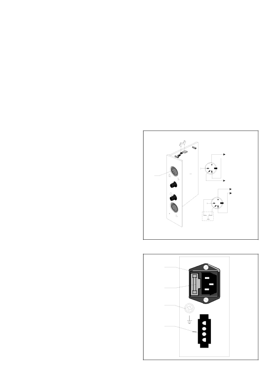
remove the mains power cable (cord) from the socket, and carefully insert a medium sized screwdriver under the small lip of the fuse cover (nearest the socket pins), and gently twist the screwdriver to lever the fuse holder out. A ‘Mate-N-Lok’ emergency supply socket (fig.4.3D) is provided to allow a +48 VDC supply to be connected.

An Earth terminal (fig.4.3C) is mounted on the Power Supply Module to allow an extra earth (ground) wire to be connected for use with the Emergency Power Supply, or when the mains power earth is inadequate.

output (fig.4.2A).

These feed the inputs of their respective amplifiers. Both signals are terminated on 5- pole 180° DIN sockets, see fig.4.2 for wiring details. For amplifier surveillance purposes, it is possible to activate the built-in pilot tone generator by means of a switch (fig.4.2E) and to adjust the volume level (fig.4.2F).

The module is fitted on the frontpanel with two potentiometers; Alarm Volume Control (fig.4.2C) and Attention Tone Volume Control (fig.4.2B).

E F

D

C

B

A

symmetric Call Out

4 1

2

5 3

Test signal 20 kHz

symmetric Music out

4 1

2

5 3

SM30 relay not active during Call.

These allow the installer to set the output volume of the internal signal generator to the desired level for each of the two types of signal tone.

The output volume level of the Call signal has no preset (setting is done on both the Microphone Input Module and the Call Station Input Module).

Power Supply Module

This module contains the terminations for both the mains power and emergency +48 VDC supply. The mains power socket (fig.4.3A) is of the standard “Europlug” type, and has a mains fuse holder built in. To remove the mains fuse (fig.4.3B), first

Fig. 4.2

A

B

C

D

+48

Fig. 4.3

10

Image 12
Contents SM30 Contents Introduction Control CentreProgramming Signal generator Emergency Power Supply +48 VDCBlock diagram SM30 plug-in modulesBlock diagram System Operation Typical OperationActivation of Control Relays Volume Control Override Relays Power on delayAlarm interrupt Signal description Alarm TonesTime signals ON/OFF Power Switch fig.4.1A Front panel controlsProgramming Keys fig.4.1C Alpha-Numeric LCD Display fig.4.1D Music Function Keys fig.4.1EPower Supply Module SM30 basic modulesLine Output Module Setting UP the Hardware GeneralOpening the housing Removing Module Blank PanelsMounting the Modules Voltage Setting Volt Emergency Power SupplyEarth Terminal ground Mounting in a 19 rack Removing FeetCalculating Required Rack Space General RulesConnecting amplifiers One Channel System fig.5.5.2Rack Mounting 1 Two channel system 2 One channel system Electret condenser microphone Built-in CompressorBalanced Line Level output Operating controls Numeric Keypad fig.6.1JCall Station ‘Press-To-Talk’ Key fig.6.1HInstallation Loudspeaker Zone Template AdjustmentsLED Intensity Preset Using the Call Station Using the Keypad to make a CallPage Installation Mounting in the Control Centre Adjustments Volume Level ControlsCall Station Input Module CSM Connection of Call StationsOperation Remote Switching Function Microphone Input Module MIMLine Input Facility Bass Cut FacilityAdjustments Gain Control Potentiometers Connection of MicrophonesControl Input Module CIMWiring control inputs Direct routingAdjustments Output Volume Control Automatic Gain ControlHeadphone Monitoring Microphone InputSafety Features Numerical order, commencing with messageRecording a Message Recording over an Existing MessageRemote Location Recording Music Input ModuleMUM Music Source InputsProgramming Software routing to zones Display music source statusZone Relay Module ZRMTerminations Coupling Zone Relay Modules Multiple Amplifier ConfigurationsControl Relay Module CRMRemote Volume Control Overrides InstallationWiring Control Relays Programming Power-on delayProgram step Selection User password ProgrammingSummary SM30 User Programming User Programming Mode IntroductionGeneral User ProgramCall Stations Signal number selection Main menu selectionCall Station number selection Key Pad SelectionKey Signal number selection Function Key number selectionKey programming selection Key Priority selectionKey Music volume up Key Music volume downKey Relay switching selection Key Music on/offMicrophones Microphone number selectionCall Routing to Zones Microphones Programming next microphoneControl Inputs Control input number selectionControl input Priority level selection inputControl Inputs Programming Control RelaysSM30 System Specification GeneralMains Supply Audio signal level diagram DL LReturn to ‘RUN’ mode Error MessagesMusic Routing Music RoutingPage Supplement Instructions for installation Contents Installer programming stepsselection Extended Call Station ProgrammingSetup Installer mode System downLanguage selection Store hardwarePower-on Delay POWER-ON DelayDelay time Music Input TextSelect Language Alternative Music Input TextInput number selection Alternative text selectionStoring Hardware Selecting Amplifier Configuration Store Hardware Amplifier ConfigurationConfiguration display Altering selectionVolume Step/Repeat Remote Volume Control MusicMode display Volume Control Routing Limits Call Override Relays Station Override RelaysRelay selection Call Station selectionRouting setting Routing LimitsDirect Routing Current zone displayClear Memory Control Alarm Mode Power-on delay System downClearing Memory 14.2 ConfirmationFlexible F-keys Extended Call Station Extended Call Station ProgrammingSelection Call Station input number 17.3 ConfirmationMPL if IE R C ONF IG Xxxxxx R MA N Singl E AMP LIF IE RS MU SIC Z on ES SE T ROU TIN G VIA Inst AL LE R P Rogr AM EL ECT PR Ogram CT L AL AR M MOD E SEL ECT FUN Ction MIC ROP Hone Priority Page Page 3922 988 33415 20/97