Philips SM30 manual Extended Call Station Programming, Selection Call Station input number

Page 64

14.7.17EXTENDED CALL STATION PROGRAMMING

The SM30 system with more than 18 loudspeaker zones needs one Module Frame LBB 1291/40 and eventually one or more Extended Call Stations LBB 9568/36 (Call Station with 36 zone confirmation LEDs). An extended Call Station requires both inputs of the Call Station Input Module.

The Module Frame contains the extra Zone Relay Modules and eventually the extra Control Relay Module(s) and Control Input Module(s).

For detailed information of the Module Frame, see the Instructions for use packed with the Module Frame.

17.1Main menu selection

Select from the main menu by means of the left/right arrow keys:

EXTENDED CALL ST.

17.2Selection Call Station input number

Select the Call Station input number (1, 3 or 5) by means of the up/down arrow keys.

17.3Confirmation

Confirm the used inputs for Extended Call Stations by means of the /O keys.

CST input 1 coupled to input 2. CST input 3 coupled to input 4. CST input 5 coupled to input 6.
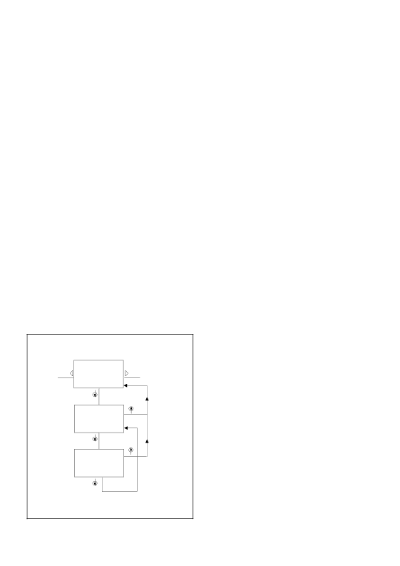
1

2

17

SELECT PROGRAM :

EXTENDED CALLST

SELECT ITEM :

CALL STATION : X

3

X=1,3,5

SELECT ITEM :

EXTEND CST: X:-

I/O

Extended Call Station

12

Image 64
Contents SM30 Contents Control Centre IntroductionProgramming Signal generator Emergency Power Supply +48 VDCBlock diagram SM30 plug-in modulesBlock diagram Typical Operation System OperationActivation of Control Relays Power on delay Volume Control Override RelaysAlarm interrupt Signal description Alarm TonesTime signals Front panel controls ON/OFF Power Switch fig.4.1AProgramming Keys fig.4.1C Alpha-Numeric LCD Display fig.4.1D Music Function Keys fig.4.1ESM30 basic modules Power Supply ModuleLine Output Module Setting UP the Hardware GeneralRemoving Module Blank Panels Opening the housingMounting the Modules Volt Emergency Power Supply Voltage SettingEarth Terminal ground Mounting in a 19 rack Removing FeetCalculating Required Rack Space General RulesOne Channel System fig.5.5.2 Connecting amplifiersRack Mounting 1 Two channel system 2 One channel system Electret condenser microphone Built-in CompressorBalanced Line Level output Operating controls Numeric Keypad fig.6.1JCall Station ‘Press-To-Talk’ Key fig.6.1HInstallation Loudspeaker Zone Template AdjustmentsLED Intensity Preset Using the Call Station Using the Keypad to make a CallPage Installation Mounting in the Control Centre Adjustments Volume Level ControlsCall Station Input Module CSM Connection of Call StationsOperation Remote Switching Function Microphone Input Module MIMLine Input Facility Bass Cut FacilityAdjustments Gain Control Potentiometers Connection of MicrophonesControl Input Module CIMWiring control inputs Direct routingAdjustments Output Volume Control Automatic Gain ControlHeadphone Monitoring Microphone InputSafety Features Numerical order, commencing with messageRecording a Message Recording over an Existing MessageRemote Location Recording Music Input ModuleMUM Music Source InputsProgramming Software routing to zones Display music source statusZRM Zone Relay ModuleTerminations Coupling Zone Relay Modules Multiple Amplifier ConfigurationsControl Relay Module CRMRemote Volume Control Overrides InstallationWiring Control Relays Programming Power-on delayProgramming Program step Selection User passwordSummary SM30 User Programming User Programming Mode IntroductionGeneral User ProgramCall Stations Signal number selection Main menu selectionCall Station number selection Key Pad SelectionKey Signal number selection Function Key number selectionKey programming selection Key Priority selectionKey Music volume up Key Music volume downKey Relay switching selection Key Music on/offMicrophone number selection MicrophonesCall Routing to Zones Microphones Programming next microphoneControl Inputs Control input number selectionControl input Priority level selection inputControl Inputs Programming Control RelaysSM30 System Specification GeneralMains Supply Audio signal level diagram DL LReturn to ‘RUN’ mode Error MessagesMusic Routing Music RoutingPage Supplement Instructions for installation Contents Installer programming stepsselection Extended Call Station ProgrammingSetup Installer mode System downLanguage selection Store hardwarePower-on Delay POWER-ON DelayDelay time Music Input TextSelect Language Alternative Music Input TextInput number selection Alternative text selectionStoring Hardware Selecting Amplifier Configuration Store Hardware Amplifier ConfigurationConfiguration display Altering selectionRemote Volume Control Music Volume Step/RepeatMode display Volume Control Routing Limits Call Override Relays Station Override RelaysRelay selection Call Station selectionRouting setting Routing LimitsDirect Routing Current zone displayClear Memory Control Alarm Mode Power-on delay System downClearing Memory 14.2 ConfirmationFlexible F-keys Extended Call Station Extended Call Station ProgrammingSelection Call Station input number 17.3 ConfirmationMPL if IE R C ONF IG Xxxxxx R MA N Singl E AMP LIF IE RS MU SIC Z on ES SE T ROU TIN G VIA Inst AL LE R P Rogr AM EL ECT PR Ogram CT L AL AR M MOD E SEL ECT FUN Ction MIC ROP Hone Priority Page Page 3922 988 33415 20/97