Emerson IP221 appendix Sensors, Gap sensors, Hi-Sens cylindrical sensors

Page 3

1. Introduction

The Mobrey Electropulse system is used for the detection of liquids or liquids with suspended / settled solids. It consists of three units, a sensor, a head amplifier unit, and a control room unit.

1.1 Sensors

There are many different Mobrey sensors available, but they fall into two categories:

a) Gap sensors

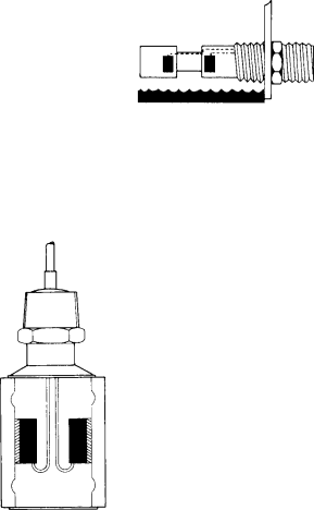
Figure 1.1 - Gap sensor, cut away to show construction

Gap sensors feature two ultrasonic transducers mounted one either side of the gap. When immersed in a liquid the signal transmitted is carried by the liquid across the gap, to the receiver, when the liquid level drops below the sensor, the signal cannot be carried across the gap, and is not received by the second transducer.

b) Hi-Sens cylindrical sensors

Figure 1.2 - Hi-Sens, cut- away to show construction

The Hi-Sens sensor consists of two ultrasonic transducers mounted on the inside of a cylinder. When the sensor is not submersed in the liquid the signal from one transducer resonates round the cylinder like a bell ringing. If the liquid rises up around the sensor, this ringing is damped and the signal received by the second transducer is significantly reduced. This reduction is monitored by the head amplifier unit. Switching occurs when the liquid is about half way up the cylinder.

Use of Hi-Sens transducers in high alarm applications, and gap sensors in low level alarm applications achieves a Failsafe system in which any sensor or cable failure will be indicated as a fault or an alarm by the control unit.

3

Image 3
Contents Fault Finding Specification and description ContentsSafety Information Introduction InstallationExplanation of symbols Protection of permanently installed equipmentSensors Gap sensorsHi-Sens cylindrical sensors Reflection Method Figure Interface detection Attenuation method FigureSolids Density Detection Head Amplifier UnitsNormal acting head amplifiers Control Units Ii Inverse acting head amplifiersType Industrial Case Marine Sensor State OutputHead amplifier internals Installation 2.1 CalibrationCalibration procedure by sensor type Hi-Sens Sensors Ii Gap SensorsIii Interface Sensors Attenuation Method Sludge Sensor Iv Interface Sensors Reflection MethodAdjacent head amplifier mounting details Sensor and head amplifier installationPage Wiring Cable Control unit installationIi Head Amplifier Unit Iii Control unitRelay Ratings Control Unit Connections Intrinsically safe installation Certificates of ConformityII 1 G EExia IIC EN 50014 & EN Relay contacts not changing Fault FindingFault indicated Unit not switchingHead Amplifiers Sensor specificationHousing Power consumptionIntrinsic safety Temperature RangeRecommended Spare Parts 5.1 Sensor and head amplifier Standard Control UnitRack Mounted Unit Sensor Connection Intrinsic Safety Mounting Sensor Type Test SwitchAppendix I Part Numbers OptionsRacks Intrinsic Safety Mounting Mains Voltage Output RelayAppendix III List of tables Section Title Appendix II List of illustrations Section TitleMaintenance / Inspection International Americas Abcdef