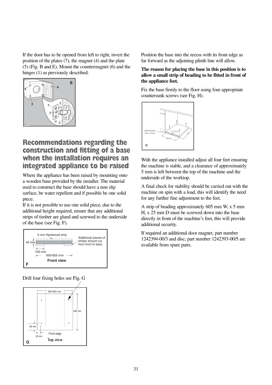
Electrolux EWD 1419 I manual Unpacking, Positioning, Water inlet

Page 26

Unpacking

All transit bolts and packing must be removed before using the appliance.

You are advised to keep all the packaging for re-use in case the machine is to be transported again.

Using a spanner unscrew and remove the rear right bolt.

Set the machine upright and remove the two remaining bolts from the back.

Pull out the three plastic spacers from the holes into which the bolts were fitted.

Plug the open holes with the plugs supplied with the instruction booklet.

Lay the machine gently on its back, making sure that the hoses are not squashed.
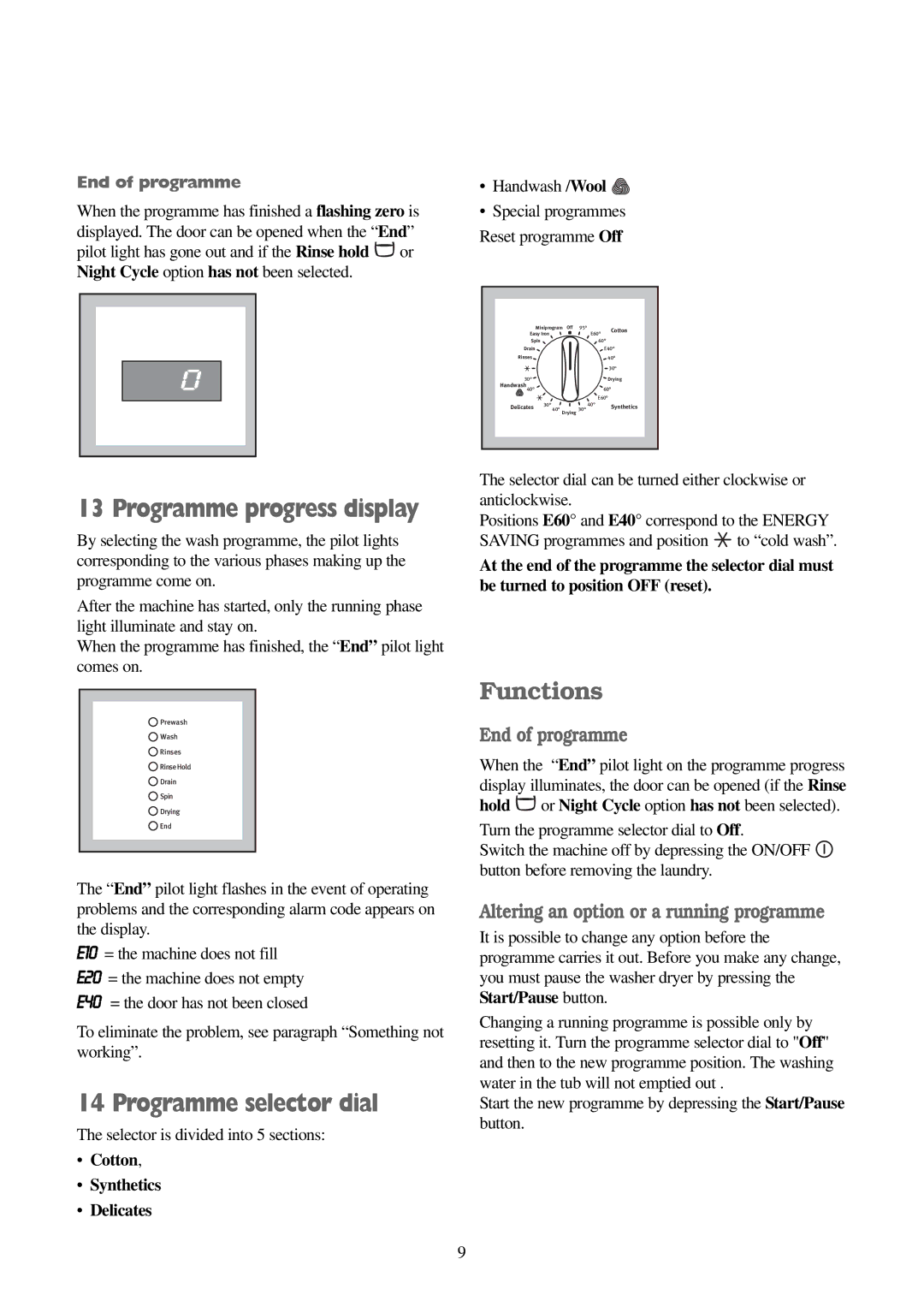
P0256

P0020

Remove the polystyrene base and take off the bottom panel by unscrewing the central screw. Carefully slide out the right polythene bag.

Positioning

Install the machine on a flat hard floor.

Make sure that air circulation around the machine is not impeded by carpets, rugs etc. Check that the machine

P0457

P0015

does not touch the wall or other kitchen units.

Never place cardboard, wood or similar materials under the machine to compensate for any unevenness in the floor.

Your new washer-dryer has been designed to be permanently plumbed in to your home’s water supply and drainage system. However, if this is not possible, it may be connected to a suitable existing tap with the drain hose discharging into a sink.

Repeat the operation for the left and central polythene bags.

Re-fit the bottom panel using the 4 screws supplied with the door hinges (in the plastic bag) and the previously removed screw.

The appliance has an inlet hose, with female 3/4” BSP thread connector. If this connection is not compatible with the plumbing of the existing installation, a variety of connectors are available from good hardware stores and plumbers merchants to suit most domestic plumbing. Any alteration to your existing plumbing

P0016

P0453

must be carried out by a competent person, or qualified plumber.

Water inlet

Connect the hose to a tap with a 3/4’’ thread. Do not use previously employed hoses.

Installation should comply with local water authority and building regulations’ requirements.

The appliance must be connected to a cold water supply.

A minimum water pressure of 0.05 MPa (0.5 bar) is required for safe operation of the appliance

26

Image 26
Contents Instruction Booklet Use InstallationChild Safety Contents Interest Environment Your New Washer-DryerEcological hints Detergent dispenser drawer Child safety featureDescription of the Appliance ON/OFF button Control PanelMAINS-ONlight Prewash buttonNight cycle button Delay start buttonQuick wash button Sensitive buttonNow you can select a new programme Selected drying time is displayed in minutesAltering an option or a running programme Programme selector dialEnd of programme Cotton Synthetics DelicatesOpening the door after the programme has started Programme informationInterrupting a programme Load the laundry Switch the machine onOperating Sequence Select the required programmeSelect the required options Select the Delay Start optionSelect the Spin speed or Rinse Hold option Start the programmeDrying only Automatic washing and drying NON-STOP programmeWashing and Drying Hints 1000g = 1 kgLaundry and placed in the tumble dryer Which detergent?Which form? Wash Care Symbols Important NotesFabric Description Washing ProgrammesType Programme Additional Max MinProgramme description Functions Load Special ProgrammesAdditional Max Night cycle optionExtra dry Drying ProgrammesType of fabric Max. load Spin speed Drying time Store dryMaintenance and Cleaning Emergency emptying out Water inlet filterSomething Not Working 0870 5 Service & Spare PartsSymptom Possible causes European guarantee Guarantee ConditionsStandard guarantee conditions CustomerWashing Installation InstructionsTechnical Specifications DryingPositioning Install the machine on a flat hard floorUnpacking Water inletInto a drainage standpipe Water drainageJoining piece must have an internal diameter of 18mm StandpipeInterest of the environment LevellingSpecial conditions Blue- Neutral Brown- Live Electrical connectionPermanent connection Preparation and assembly of the door Building-inDrill four fixing holes see Fig. G Electrolux plc