NEC N8103-102 manual Installing BBU in Server

Page 52

30

1-5. Installing BBU in Server

Install the BBU in the disk array controller and the server in the following procedure:

1.Remove the additional slot cover and screw from an unused PCI slot. Remove the cables from the disk array controller.

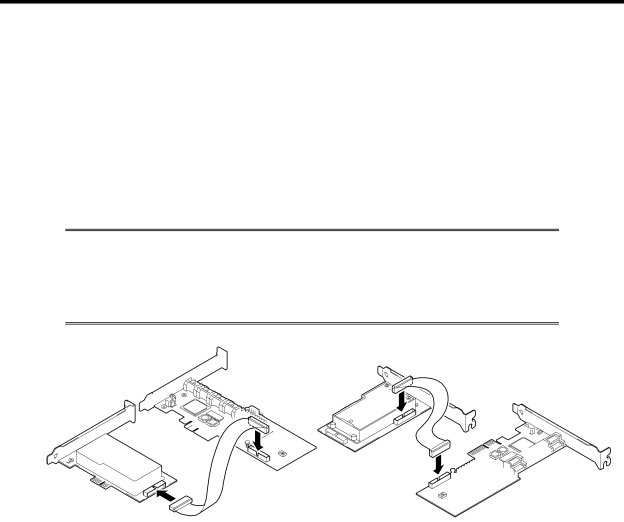
2.Remove the disk array controller from the server, and connect the battery cable to the battery connector on the disk array controller.

NOTE: The BBU has two battery cable connectors. Either of two connectors may be used. Select either connector appropriate to your system environment (e.g., location to install in the server and cable routing condition) to connect the battery cable.

Image 52
Contents 増設バッテリ ユーザーズガイド 商標について まえがき Preface使用上のご注意 ~必ずお読みください~ 安全に関わる表示についてIii Symbols Used in This Manual and Warning Labels 本書で使用する記号とその内容Prohibited Actions Mandatory Action安全上のご注意 Safety IndicationsGeneral 装置内に水や異物を入れない Keep water or foreign matter away from the serverPower Supply and Power Cord Use 電源がONのまま取り付け・取り外しをしない破損したケーブルを使用しない ぬれた手で電源コードをもたない指定以外のインタフェースケーブルを使用しない Installation, Relocation, Storage, and ConnectionDo not use any unauthorized interface cable 腐食性ガスの存在する環境で使用または保管しない Avoid installation in extreme temperature conditions高温注意 Cleaning and Working with the Product 自分で分解・修理・改造はしないプラグを差し込んだまま取り扱わない 中途半端に取り付けないDuring Operation 雷がなったら触らないペットを近づけない 近くで携帯電話やPHSを使用しない警告ラベルについて 使用上のご注意 ~装置を正しく動作させるために~ This Manual 本書についてText Conventions 梱包箱の中身について Package輸送について Transportation第三者への譲渡について Transfer to Third PartyHDD内のデータについて About data on the hard diskMaintenance Parts 製品寿命についてLife of BBU 保守用部品についてリサイクル・廃棄について Recycle and Disposal章 概要 Contents 章 概要 本製品の特徴最大データバックアップ時間 取り付け作業の流れ 本製品を取り付ける作業の流れは以下の通りです。詳しい作業内容については、それぞれ 対応する章をご覧になってください。梱包箱の中身を確認する 各部の名称と機能 本製品表面本製品裏面添付品 取り付け時の注意事項 注意事項運用時の注意事項 Page 取り付け手順 PCI スロットの選択ブラケットの選択・取り付け バッテリラベルの貼り付けサイドカバーの取り外し 本製品の取り付け本体装置のサイドカバーや電源コードおよびディスクアレイコントローラに接続 されたケーブルを元通りに取り付けます。 ユーティリティからの確認 „ ご購入時のバッテリパックは充電されていません。その場合は、WebPAM 保守サービス 予防保守本製品の予防保守 バッテリパックの寿命バッテリパックの交換手順 バッテリケースのコネクタからバッテリパックのケーブルを取り外します。 バッテリケースからバッテリパックを外します。 12. 本製品の裏面から、手順 7 で外したネジ4 本でバッテリパックを固定します。 Set up Date ) Y 2006 . M15. 本製品とディスクアレイコントローラを本体装置の PCI スロットに元通りに取り 付けてネジ止めします。 Characteristics of BBU OverviewSpecification Installation FlowChecking Contents in Package Names and Functions of Sections Front viewRear view Accessories Page Installation Procedure Selecting PCI SlotSelecting and Installing Bracket Putting Battery Label Removing Side Cover on ServerInstalling BBU in Server Screw Disk array controller Screws BBU Battery cable Checking by Utility Maintenance Service Preventive MaintenancePreventive Maintenance of BBU Life of Battery PackBattery Pack Replacement Procedure Battery pack Battery case New replaced battery pack Battery case Fill the year and month. Example Y 2006.M Disk array controller Screws BBU