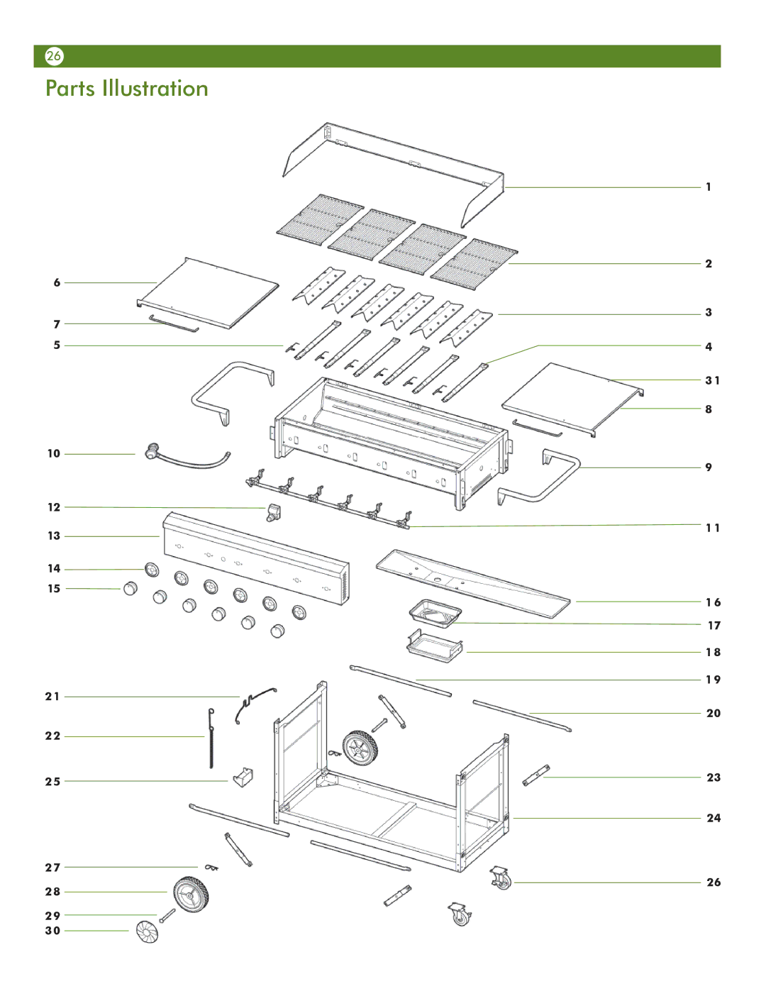
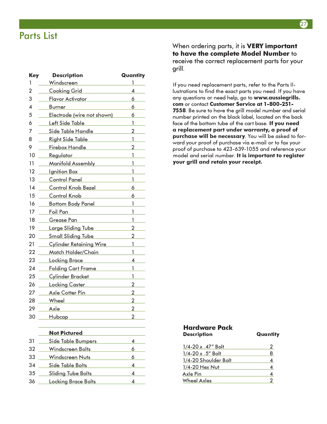
Aussie 69F6U00KS1 manual Parts List, Key Description Quantity, Not Pictured

Page 27

Parts List

Key

Description

Quantity

1


Windscreen

1

2


Cooking Grid

4

3


Flavor Activator

6

4


Burner

6

5


Electrode (wire not shown)

6

6


Left Side Table

1

7


Side Table Handle

2

8


Right Side Table

1

9


Firebox Handle

2

10


Regulator

1

11


Manifold Assembly

1

12


Ignition Box

1

13


Control Panel

1

14


Control Knob Bezel

6

15


Control Knob

6

16


Bottom Body Panel

1

17


Foil Pan

1

18


Grease Pan

1

19


Large Sliding Tube

2

20


Small Sliding Tube

2

21


Cylinder Retaining Wire

1

22


Match Holder/Chain

1

23


Locking Brace

4

24


Folding Cart Frame

1

25


Cylinder Bracket

1

26


Locking Caster

2

27


Axle Cotter Pin

2

28


Wheel

2

29


Axle

2

30


Hubcap

2


Not Pictured


31

Side Table Bumpers

4

32

Windscreen Bolts

6

33

Windscreen Nuts

6

34

Side Table Bolts

4

35

Sliding Tube Bolts

4

36

Locking Brace Bolts

4

27

When ordering parts, it is VERY important to have the complete Model Number to receive the correct replacement parts for your grill.

If you need replacement parts, refer to the Parts Il- lustrations to find the exact parts you need. If you have any questions or need help, go to www.aussiegrills. com or contact Customer Service at 1-800-251- 7558. Be sure to have the grill model number and serial number printed on the black label, located on the back face of the bottom tube of the cart base. If you need a replacement part under warranty, a proof of purchase will be necessary. You will be asked to for- ward your proof of purchase via e-mail or to fax your proof of purchase to 423-639-1055 and reference your model and serial number. It is important to register your grill and retain your receipt.

Hardware Pack

Description

Quantity

1/4-20 x .47” Bolt

2


1/4-20 x .5” Bolt

8


1/4-20

Shoulder Bolt

4


1/4-20

Hex Nut

4


Axle Pin

4


Wheel Axles

2


Image 27
Contents Sets Up In Minutes Great for Every Occasion Six Burner Event GrillCarbon Monoxide Hazard Tools Required for AssemblyContents Preparation for AssemblyPacking List Step Attaching the Firebox Handles Assembly InstructionsStep Attaching the Wheels and Casters Step Attaching Cylinder BracketSet-Up Instructions Step Unfolding CartStep Unfolding Firebox Handles Latch Latch Catch Step Placing the Grill Body on the CartStep Flavor Activator / Cooking Grid Assembly Folding/Preparation for Transport Connecting/Disconnecting the Gas Using GasLP Gas Cylinder Connecting LP Gas Cylinder Disconnecting LP Gas CylinderLP Hose and Regulator Performing a Leak Test Before Using Your LP Gas GrillInstallation Codes Selecting a LocationHow to Perform a Leak Test First Time USE and as required Hose Connection Tubular Burner ends Lighting the Grill Using the Pulse-Spark Ignitor Manual Lighting of the Grill on Check the Flame Manually Lighting the GrillGrill Cooking Direct Method Cooking On the Gas GrillDirect Cooking on the Grids End of Cooking SessionCleaning the Grill Care and MaintenanceHow to Clean the Burners Bottom Body Panel Removal Storage and Transportation Emergencies TroubleshootingClean the Burners. See How to Clean Burners in Care MaintenanceSee How to Clean Burners in Care and Maintenance Important Notice Parts Illustration Description Quantity Parts ListKey Description Quantity Not PicturedMeco Corporation Limited Warranty Limited Warranty