Sony NW-MS6 service manual Section Exploded Views, General Section, 17 18

Page 39

NW-MS6

NOTE:

-XX and -X mean standardized parts, so they may have some difference from the original one.

Color Indication of Appearance Parts Example:

KNOB, BALANCE (WHITE) . . . (RED)

↑ ↑

Parts Color Cabinet's Color
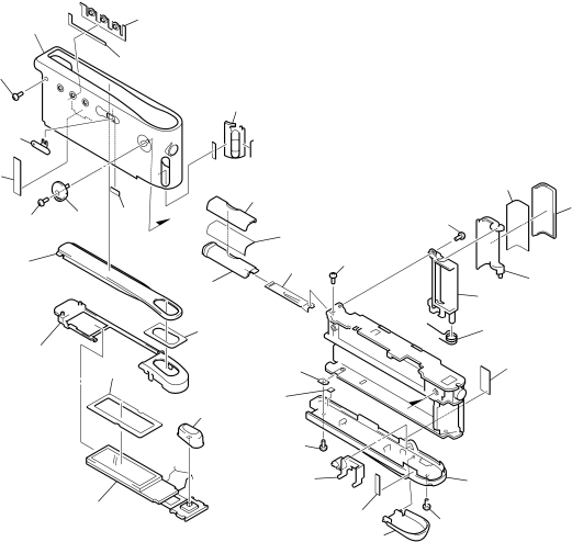
SECTION 6

EXPLODED VIEWS

Items marked “*” are not stocked since they are seldom required for routine service. Some delay should be anticipated when ordering these items.

The mechanical parts with no reference num- ber in the exploded views are not supplied.

Accessories and packing materials are given in the last of the electrical parts list.

6-1. GENERAL SECTION

1

3

2

4

5

31

4 6 30

19

20

22

1718 17

28

27

29

26

4


9

24

16

8


15

21

14

11

34

33


23


10


25

13


7


not supplied


4


12


Ref. No.

Part No.

Description

Remark

Ref. No.

Part No.

Description

Remark

1

3-225-304-01

BUTTON (SUB)


18

3-225-305-01

BUTTON (VOL)


2

3-225-306-01

SHEET (SUB), ADHESIVE


19

3-225-313-01

WINDOW (LCD)


3

3-225-303-11

CASE


20

3-225-308-01

CHASSIS (LCD)


4

3-348-998-51

SCREW (M1.4X3.5), TAPPING, PAN


21

3-225-310-01 SHEET (LCD 1), ADHESIVE


5

3-225-333-01

KNOB (HOLD)


22

3-225-312-01

CUSHION (LCD)


6

X-3379-873-1

SHAFT ASSY, STRAP


23

3-225-309-01

BUTTON (PLAY)


* 7

A-3323-646-A

CONSOLE BOARD, COMPLETE


24

4-218-233-15

SCREW (1.4), MI


8

3-225-330-01

LID, BATTERY CASE


25

3-225-327-01

GUIDE (LED)


9

X-3379-871-1

TERMINAL (+) ASSY, BATTERY


26

3-225-331-01

SHEET, ADHESIVE


10

4-963-883-21

SCREW (M1.4), PRECISION PAN


27

3-225-332-01 COVER (BATTERY CASE LID)


11

3-225-704-01

PLATE, FIXED


28

3-225-323-01 SHEET (EJECT LID), ADHESIVE


12

3-225-334-01

LID (PC)


29

3-225-324-01

COVER (EJECT LID)


13

3-225-326-01

COVER (SIDE)


30

3-229-572-01

SHEET (HOLD)


14

3-225-325-01

SPRING (EJECT), TORSION


31

3-229-571-01

SHEET (EJECT)


15

3-225-316-01

GUIDE (EJECT LID)


33

3-327-119-01

SHEET, AZIMUTH


16

3-225-322-01

LID (EJECT)


34

3-309-595-11

SHEET, INSULATING, PACK


17

3-225-307-01

SHEET (VOL), ADHESIVE


39

Image 39 Contents
NW-MS6 SpecificationsNW-MS6 Table of ContentsDisassembly DiagramsNW-MS6 Section Servicing Notes NW-MS6 Section General Looking at ControlsNW-MS6 Section Disassembly Disassembly FlowCase Block Assy Case Chassis Main Assy Guide LEDConsole Assy Console UNIT, SUB BOARD, Main BoardConsole Board Preparation NW-MS6 Section Test ModeSetting the Test Mode Releasing the Test ModeFlow Chart of Operations in the Test Mode Items to Check in the Test Mode 1. ROM/RAM Self-checkDisplay of Version and Destination Checking LOW Batt Voltage Checking the Rated VoltageUSB Self-check USBMemo Block Diagram Main Section Section DiagramsGIOE6 Block Diagram DISPLAY/POWER Supply SectionSurface Waveforms Main board Location Printed Wiring Boards Main Section Uses unleaded solderNW-MS6 Schematic Diagram Main /4 See page 27 for IC Block Diagrams NW-MS6 R9032 22k C9036 33k C9037 3300p R9033 Schematic Diagram SUB /2 NW-MS6 SUB Board Component Side SUB Board Conductor Side Printed Wiring Board SUB Section Uses unleaded solderMBM29LV400BC-90PBT-SJDE1-4 SN74LV139APWR MPC18A41FCR2 IC9006 XC62HR1902MR IC PIN Function Description SDI1 WAKE1WAKE0 RXDUSB Xdreq USB XdetVbus XON Vbus INTFrale FrweFrre FrcleMSEL1, MSEL0 CLKSEL3 CLKSEL2EXTAL0 VSS0VDD3 VSS6VSS7 ADR5, ADR6Clkout VDE7Trst VSS13Section Exploded Views General Section17 18 Not supplied Main Board SectionResistors Section NW-MS6 Electrical Parts List MainDiode NW-MS6 MainVibrator Main SUBNW-MS6 SUB SwitchMemo Revision History