c. Turn the Power Lever ON.
d. Let the unit run for 30 minutes. Air will expel freely through the Coupler.
e. Turn the Power Lever OFF.
f.Unplug the Power Cord and remove the male coupler.
|
| Coupler |
| Coupler | |||
|
| Plug |
| Plug | |||
Tool |
|
|
|
|
| ||
Quick |
| Air Hose | |||||
|
|
| |||||
|
| Coupler |
| ||||
|
|
|
|
|
| on Reel | |
Shut |
|
|
|
|
| ||
Off | Oiler | Filter | |||||
Valve | |||||||
|
|
|
| Air | |||
|
|
|
|
|
| ||
|
|
|
|
|
| ||
|
|
|
|
|
| Compressor | |
|
|
|
|
|
| ||
|
|
|
|
|
|
| |
Quick |
|
|
|
|
| ||
Coupler |
|
|
|
|
| ||
Regulator with | |||||||
|
| ||||||
|
| Pressure Gauge | |||||
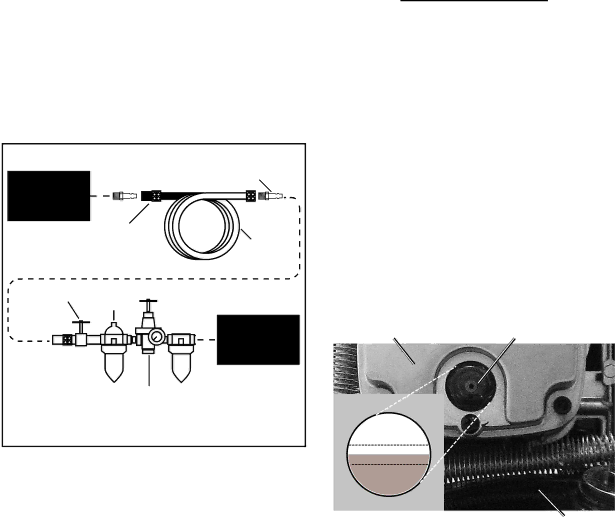
Sample Air Line Setup
5.Connect a regulator valve, an
Note: An
6.Depending on the tool which you will be using with this compressor, you may need to incorporate additional components, such as an
Consult your air tool’s manual for needed accessories.
Checking the Oil
1.Check the oil level before operation. Fill the Pump Crankcase (39) with premium quality SAE
IMPORTANT: Running the Air Compressor with the incorrect amount of oil will cause damage to the equipment and void the warranty. To prevent damage, do not use with overfilled or low oil. Slowly fill to full line, wait 2 minutes and fill back up to full line. Compressor has small passages that will fill slowly.
Crankcase Cover (31) Oil Sight Glass (33)
OIL LEVEL
overfill
full ![]()
low
Figure 5 | Tank (70) |
2.The oil level should be at the center of the “full” level on the oil level sight glass, as shown in Figure 5. Add oil as needed to maintain this level. Do not let the oil level go below the center dot (LOW as shown above) and do not overfill the oil so that it is above the center dot (OVERFILL as shown above) on the sight glass.
3.To add oil:
a.Remove the Oil Plug (37).
b.Using a funnel to avoid spills, pour enough oil into the Pump Crankcase (39) to reach the “full” level in the Oil Sight Glass (33).
Page 10 | For technical questions, please call | SKU 67847 |