Grizzly G4003G owner manual To confirm that the bearings are correctly pre- loaded

Page 42

Since it can take great effort to turn the inner spanner nut, you may find it difficult to know if you have gone past the zero end-play point or not. You may find it easiest to have some- one watch the dial for you while you tighten the inner spanner nut. If you think you may have gone past the zero end-play point, take the time to unload the bearings as described earlier, then re-tighten the inner spanner nut until you know you have reached the correct setting.

When you are confident that you have adjust- ed the inner spanner nut until zero spindle end-play and preload exists, you now must move the spanner inward and additional 0.001" to set the preload.

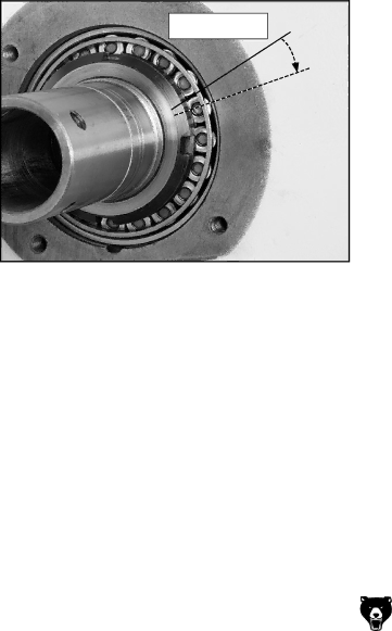
11.To set the preload, tighten the spanner nut an additional 0.16" along its circumference. See Figure 61 for the example of this measure- ment.

0.16" Travel

Figure 61. Final spanner nut rotation.

12.Without causing the inner spanner nut to tighten any further, install and tighten the outer spanner nut against the inner nut. Do not overtighten the outer spanner nut because additional preload can force the bearings even tighter against the races in the headstock and cause the headstock to com- press, crack, or cause bearing failure.

13.Position the gasket correctly, and re-install the outboard spindle cover.

To confirm that the bearings are correctly pre- loaded:

1.Make sure all safety precautions have been taken and setup steps are complete to make the lathe fully operational.

2.Install the chuck and tighten the jaws.

3.Set the spindle speed to its highest setting.

4.Connect the lathe to power and turn the lathe spindle ON.

5.Let the lathe run for 20 minutes.

6.Turn the spindle OFF, disconnect lathe from power, and check the temperature of the spindle.

—If the spindle nose is slightly warm to the touch, you have correct bearing preload.

—If the spindle nose is hotter than you can comfortably keep your hand on, the pre- load is too tight and you must repeat bear- ing preload adjustment procedure..

-40-

G4003G Gunsmith's Lathe

Image 42
Contents Model G4003G Gunsmiths Lathe Page Table of Contents Introduction ForewordContact Info Machine Data Sheet Tailstock Info Identification G4003G Gunsmiths Lathe G4003G Gunsmiths Lathe Additional Safety Instructions for Lathes Glossary of Terms 220V Single-Phase Circuit RequirementsItems Needed for Setup SetupSetup Safety UnpackingLoose Components Figure InventoryMajor Components Figure Qty Hex Wrench Set 2, 4, 5, 6, 8, 10 mm .. eaSite Considerations Clean UpPlacement Location Floor LoadTo assembly the cabinet base Mounting to ShopBolting to Concrete Floors Lifting & Moving To begin the test run & break-in procedure Test Run & Break-InTailstock Setup To align the tailstockAdjusting for tailstock end taper Spindle Speeds Operation SafetyOperation ExampleDisconnect Lathe from Power Mounting Chuck FaceplateTo install a chuck CentersSpider SpiderSteady Rest Follow Rest To use the steady restTo use the follow rest Feed Direction Lever Feed Rod LeverFeed Rate Chart Gearbox LeversHalf-Nut Lever Inch ThreadingStandard thread chart To use the chart Change Gears and Metric ThreadingCompound Slide Handwheel Carriage HandwheelsCarriage Handwheel Cross Slide HandwheelTailstock Handwheel Tool Post & HolderTailstock Controls Barrel Lock LeverAccessories Quick Change Tool HoldersH6095-Digital Readout DRO MT#3 Long Nose Center Maintenance Basic MaintenanceLubrication Slides and Ways Service TroubleshootingMotor & Gearbox Operation and Work Results Gibs Cross-slide Gib, see FigureDisconnect the Lathe from the Power Source Bearing PreloadAdjusting spindle bearings To confirm that the bearings are correctly pre- loaded Wiring-Electrical Box Electrical box wiring G4003G Gunsmiths LatheG4003G Gunsmiths Lathe Wiring-Motor & Control Panel Motor wiringG4003G Gunsmiths Lathe Wiring-Plug, Light & Spindle Switch Work light wiringG4003G Gunsmiths Lathe Parts ComponentsGearbox Gearing Gearbox Gearing Parts List Gearbox Gearbox Shifters Parts List Quick Change System Quick Change System Parts List Apron Apron Parts List Saddle Saddle Parts List Compound Slide Tailstock Lathe Bed & Motor Base Lathe Bed, Motor & Base Parts List Feed Rod Feed Rod Parts List Machine Labels Electrical Components Steady & Follow Rest Assemblies Page Page Warranty and Returns