Saint Gobain Vidros PFD1, PFS1 manual 1641, Push

Page 10

PFD1/PFS1 – OPERATING INSTRUCTIONS

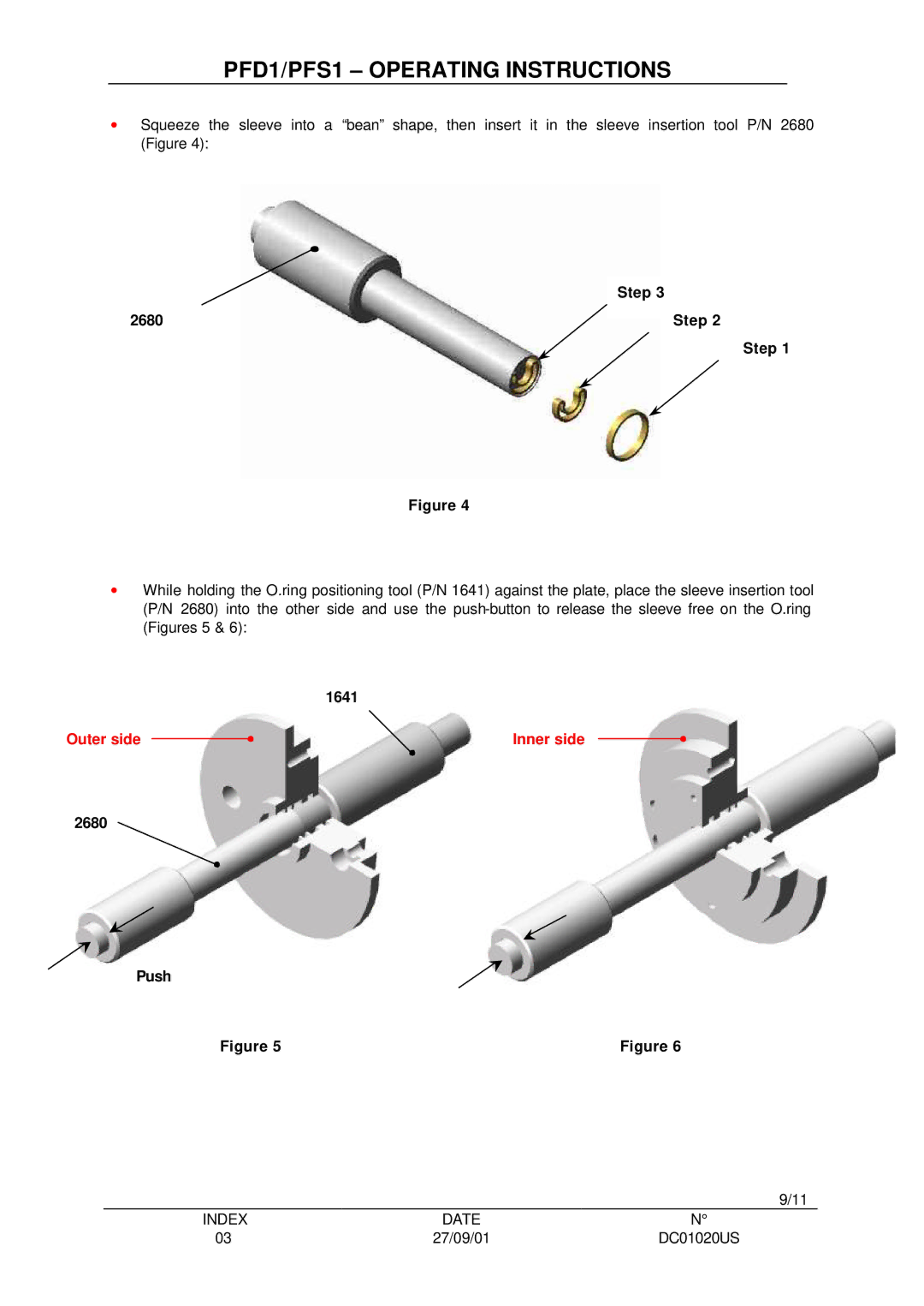
Squeeze the sleeve into a “bean” shape, then insert it in the sleeve insertion tool P/N 2680 (Figure 4):

Step 3

2680

Step 2

Step 1

Figure 4

While holding the O.ring positioning tool (P/N 1641) against the plate, place the sleeve insertion tool (P/N 2680) into the other side and use the push-button to release the sleeve free on the O.ring (Figures 5 & 6):

1641

Outer side


Inner side


2680

Push

Figure 5

Figure 6

9/11

INDEX

DATE

03

27/09/01

DC01020US

Image 10
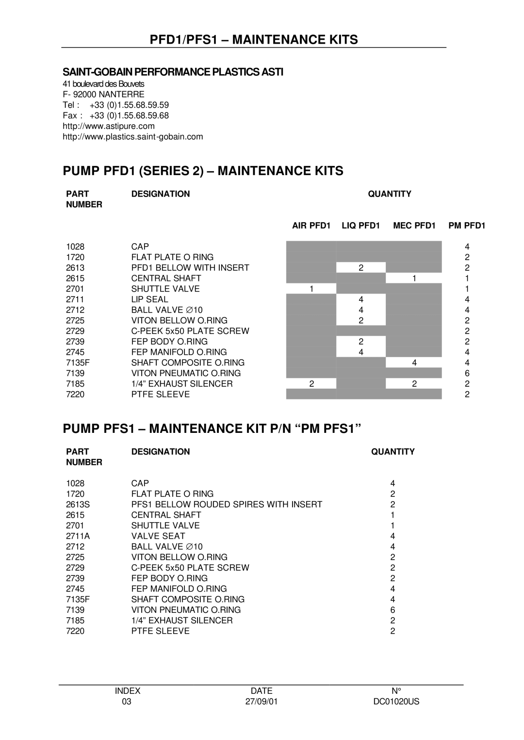
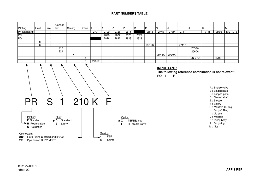
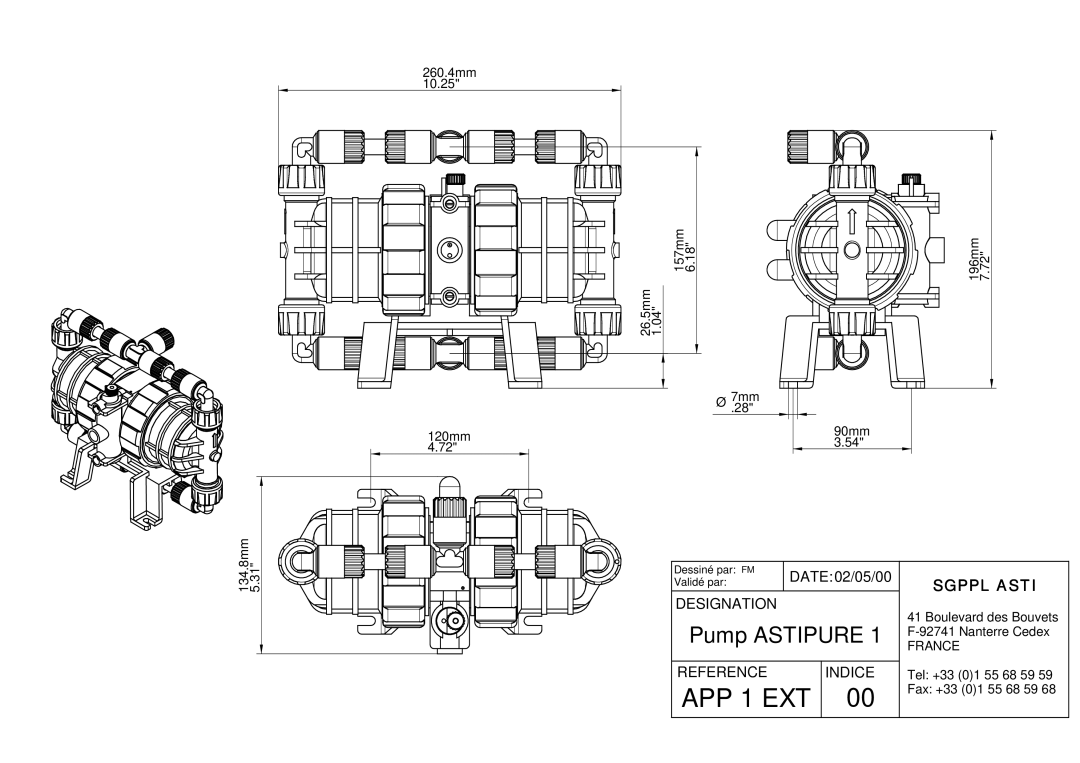
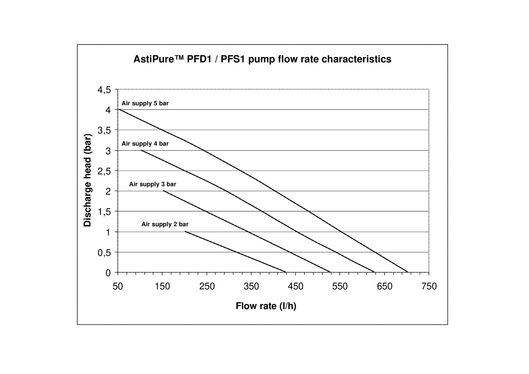
Contents PFD1/PFS1 Headquarters FactoryIndex II Quick checklist GeneralIII.2 Set up III Installation and OperationIII.1 Testing II.2 ReceptionIV Applications IV.4 Applications MaintenanceTrouble Shooting IV.5 Limitations of useIntermittent operation VI Dismantling and RepairImportant these parts should always be replaced together CommentsVI.3 Stripping and assembling the pump VI.1 How to dismantleVI.2 Examination VI.3.1 Replacing the shuttle valve7135F Ring1641 Short Long 1641 Step 26802680 Push VI.3.5 Replacing the bellow and body O.rings 1643VI.3.4 Replacing the Ptfe sleeves VI.3.6 Replacing the manifold O.ringsVII Warranty Pumps PFD1 Series 2 & PFS1 PFD1 PFS1PFD1/PFS1 Maintenance Kits APP 1 REF Part Numbers Table Following reference combination is not relevantAPP 1 EXT Air supply 4 bar Air supply 5 barAir supply 3 bar Air supply 2 bar APP 1 CAB