PFD1/PFS1 – OPERATING INSTRUCTIONS
Thank you for selecting a
I – General
I.1 – Introduction
The Model PFD/PFS is a pneumatically operated TEFLON® pump. There are no internal or external metal parts.
The pump is designed for handling corrosive, inflammable and sterile fluids. It meets the requirements of the semiconductor, pharmaceutical and chemical industries.
I.2 – Materials
All wetted parts are manufactured in TEFLON® PFA HP and PTFE.
Other parts are made of
There are no metal parts.
I.3 – Operation
The pump is pneumatically operated; two bellows joined by a central shaft reciprocate horizontally. The suction and delivery strokes alternate from one side of the pump to the other.
The pump is
The pumping frequency of a bellows pump is much slower than an equivalent diaphragm pump and results in an extended life for the bellows.
Pulsation dampers with wetted parts in TEFLON® PFA and PTFE are available as an option. This dampens the pulse by approximately 65 to 80%. The pulsation damper for the PFD1/PFS1 pump is AMC1/AMS1.
I.4 – Pump Data |
|
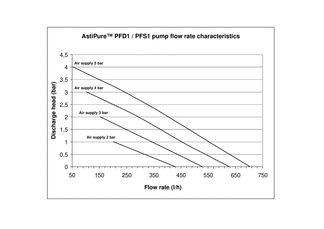
Flow rate | 2.5 GPM (600 l/h) |
Discharge pressure | 58 PSI max. (4 bar) |
Suction head | 10 feet water column (3 m) |
Max. air consumption | 6 SCFM (10 m³/h) NTP |
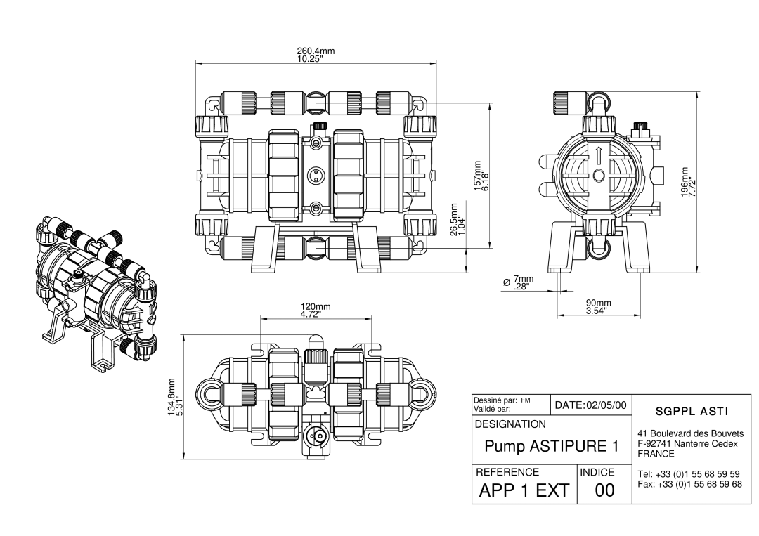
Connections | 3/8”x1/2” or 10x13 mm TEFLON® flared tube or 1/2” MNPT thread. |
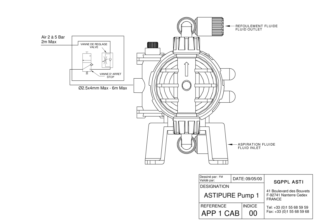
Air connection | 1/4" I/D gas female thread |
| Tubing ∅3/32”x5/32” (2.5x4 mm) maximum |
| 10 feet (3 m) < length < 20 feet (6 m) |
Weight | 4.5 lbs (2 kg) |
Also available three larger capacity pumps with optional pulsation dampers:
PFD2/PFS2 | Flow rate 5 US GPM (20 l/min) | AMC2/AMS2 |
PFD3/PFS3 | Flow rate 12.5 US GPM (50 l/min) | AMC3/AMS3 |
PFD4/PFS4 | Flow rate 25 US GPM (100 l/min) | AMC4/AMS4 |
II – Quick checklist
II.1 – Shipment
Pumps are cleaned and assembled in our clean room, then double sealed in plastic bags to ensure they are not contaminated in transit. They are then packed in cartons with Polyethylene protection.
2/11
INDEX | DATE | N° |
03 | 27/09/01 | DC01020US |
