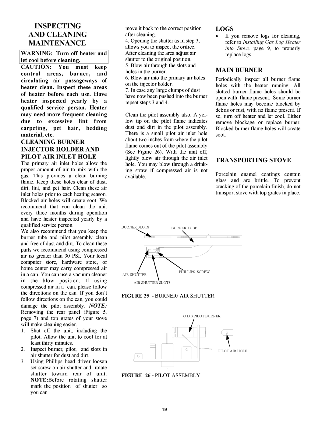
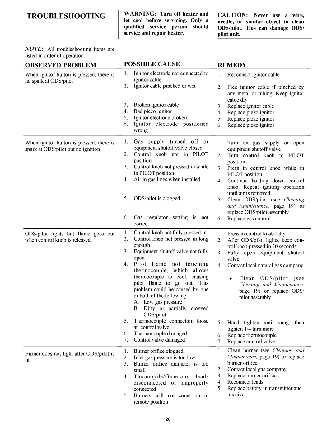
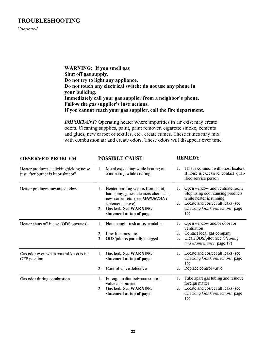
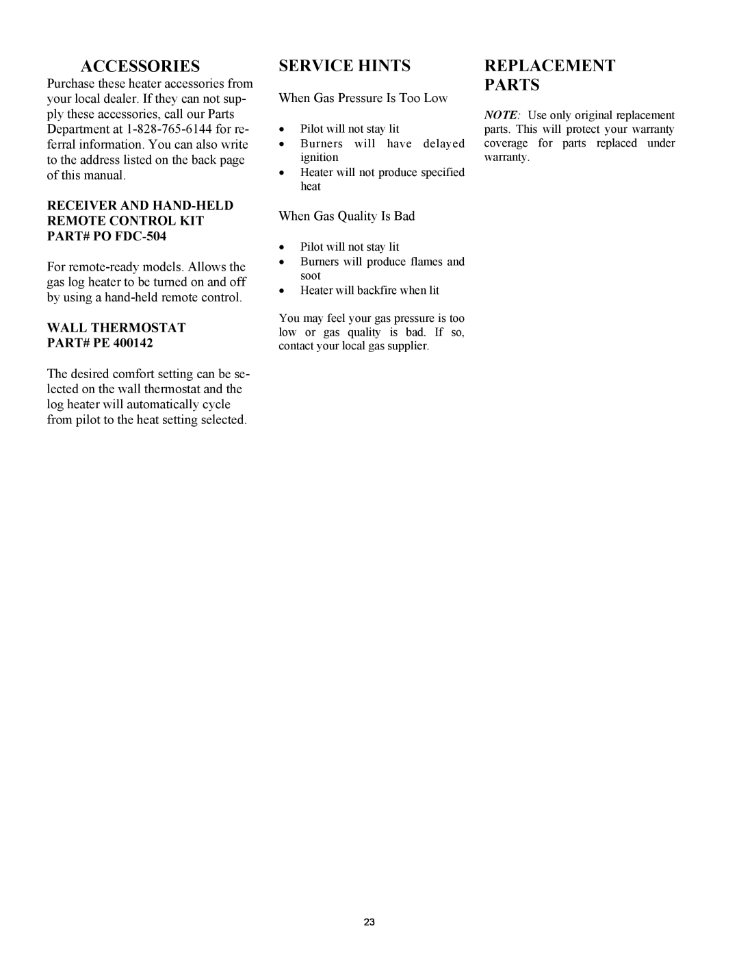
New Buck Corporation GAS STOVE HEATER installation manual Continued, Optional Remote Control

Page 22
OPTIONAL REMOTE

OPERATING HEATER

Continued

OPTIONAL REMOTE

CONTROL

NOTE: All remote control accessories must be purchased separately (see Accessories). Follow instructions included with the remote control.

NOTICE: You must light the pilot before using the remote control unit. See Lighting Instructions on page 17.

OPERATING HEATER

Continued

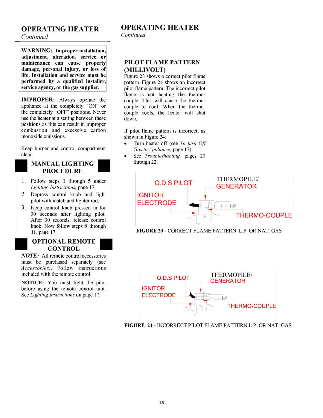
PILOT FLAME PATTERN (MILLIVOLT)

Figure 23 shows a correct pilot flame pattern. Figure 24 shows an incorrect pilot flame pattern. The incorrect pilot flame is not heating the thermo- couple. This will cause the thermo- couple to cool. When the thermo- couple cools, the heater will shut down.

If pilot flame pattern is incorrect, as shown in Figure 24:

Turn heater off (see To turn Off Gas to Appliance, page 17)

See Troubleshooting, pages 20 through 22.

THERMOPILE/

FIGURE 23 - CORRECT FLAME PATTERN L.P. OR NAT. GAS

THERMOPILE/

FIGURE 24 - INCORRECT PILOT FLAME PATTERN L.P. OR NAT. GAS

18
Image 22
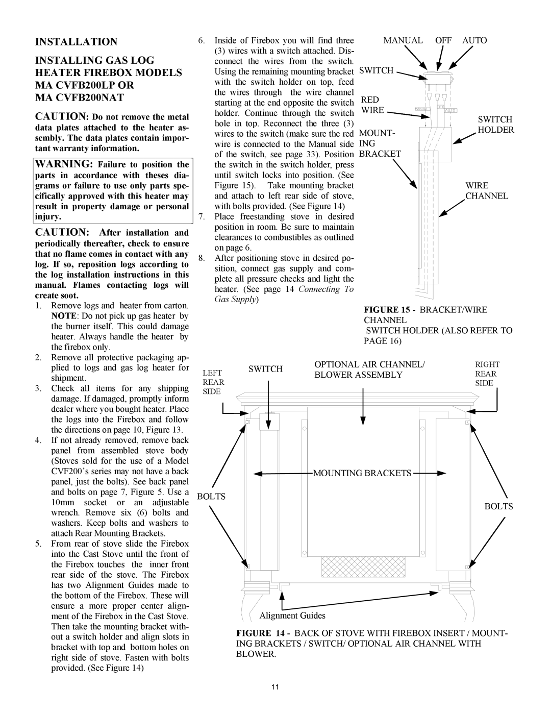
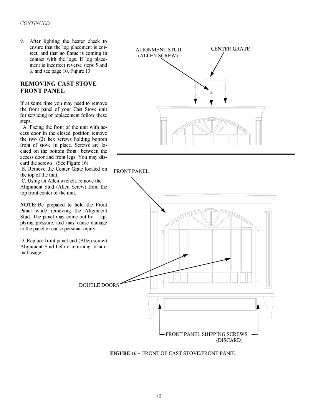
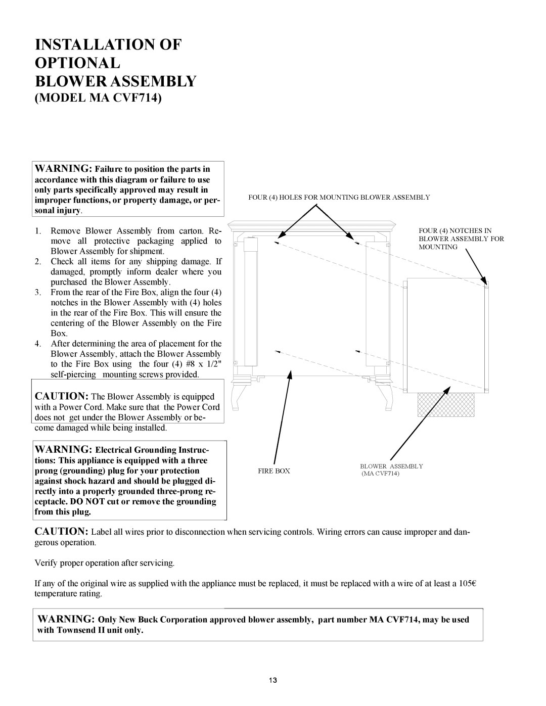
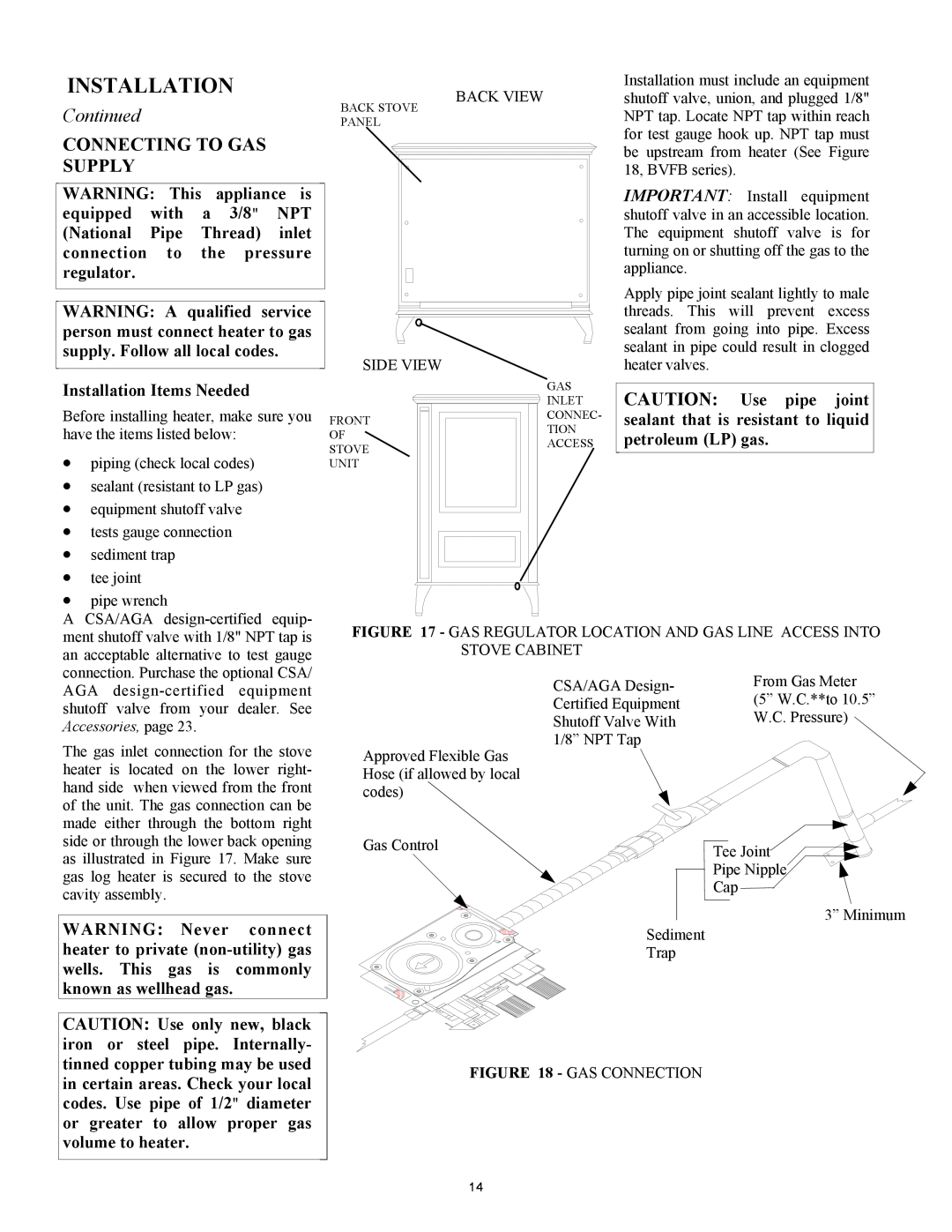
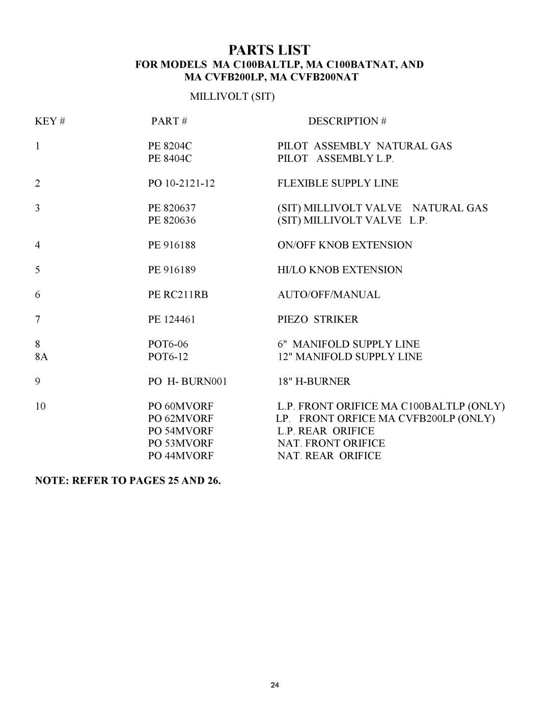
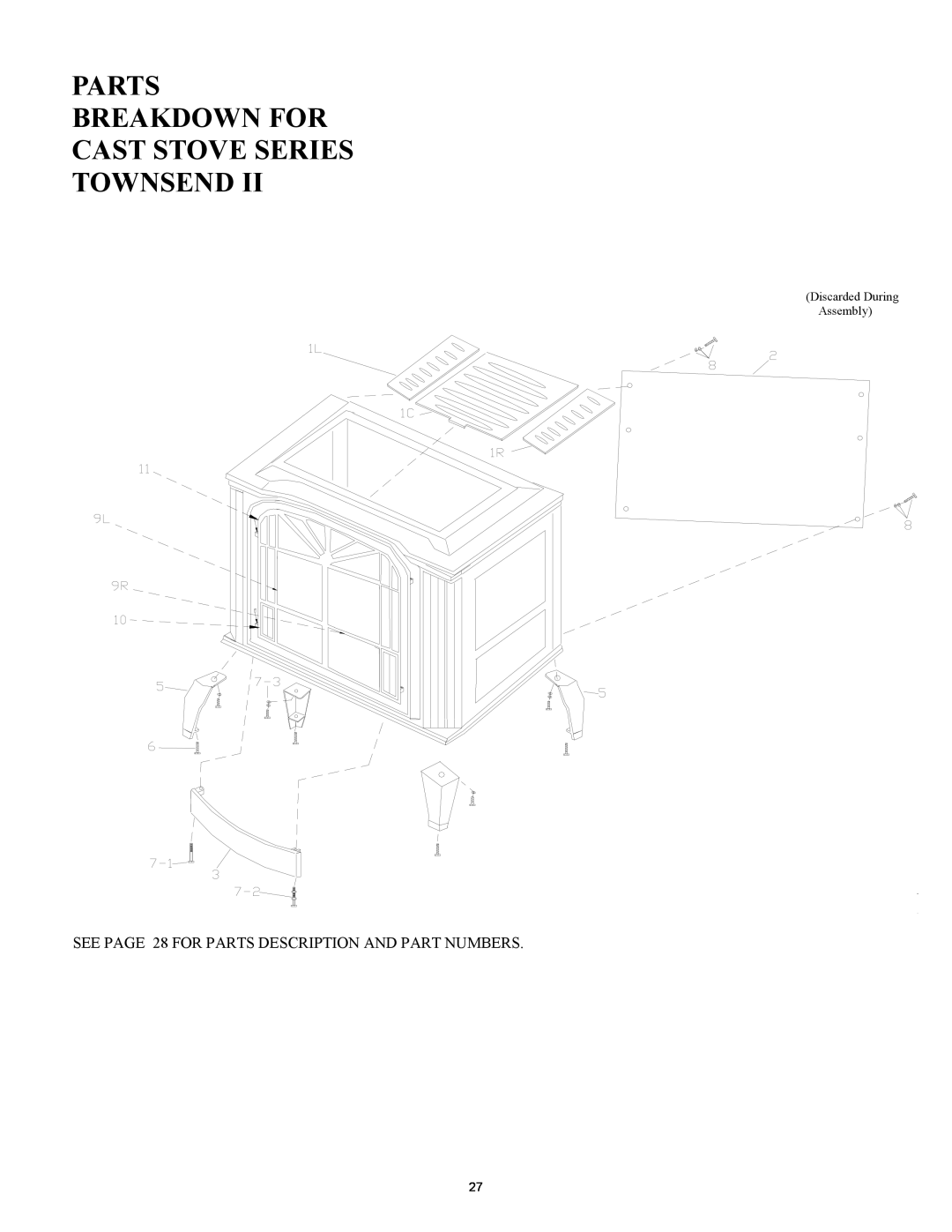
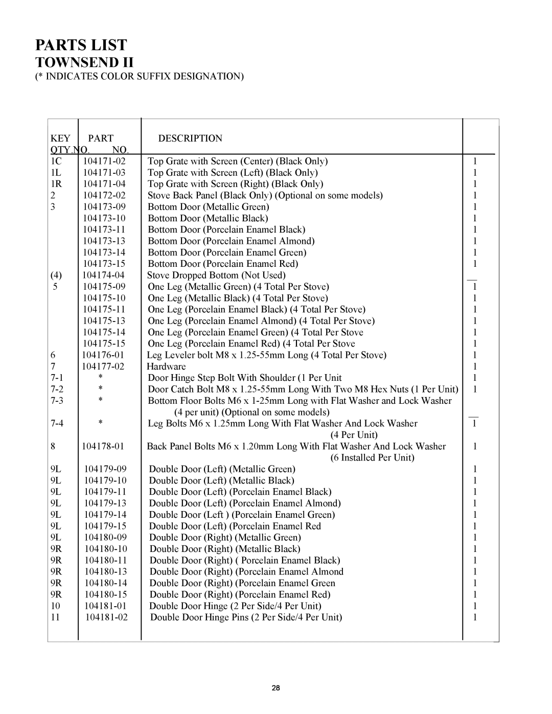
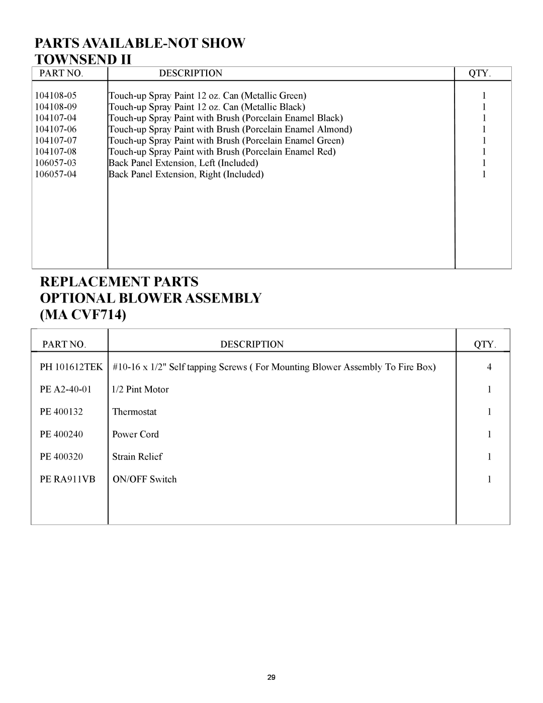
Contents Page Page TABLE OF CONTENTS IDENTIFICATION NUMBERS AND DESCRIPTIONS FOR CAST STOVE SERIESSAFETY INFORMATION WARNINGS VENT-FREENATURAL OR L.P GAS STOVE HEATERPRODUCT INDENTIFICATION PRODUCT FEATURESSAFETY PILOT LOCAL CODESUnusually Tight Construction AIR FOR COMBUSTION AND VENTILATIONPROVIDING ADEQUATE VENTILATION Confined and Unconfined SpaceContinued DETERMINING FRESH-AIRFLOW FOR HEATER LOCATIONVentilation Air From Outdoors VENTILATION AIRContinued CLEARANCES TO INSTALLATIONGAS CONNECTION COMBUSTIBLES Vent-FreeOperation OnlySTOVE CAVITY ASSEMBLY Continued10.Install door catch bolt M8 ContinuedMA C100BATNAT ContinuedIMPORTANT Make “LOG #2 PLACEMENT” MA CVFB200NAT INSTALLATIONGas Supply REMOVING CAST STOVE FRONT PANEL CONTINUEDINSTALLATION OF OPTIONAL BLOWER ASSEMBLY MODEL MA CVF714Accessories, page CONNECTING TO GAS SUPPLYInstallation Items Needed ContinuedFor purpose of input adjustment Pressure Testing Heater Gas ConnectionsPressure Testing Gas Supply Piping System ContinuedPage IGNITOR ELECTRODE FLAME ADJUSTMENT KNOB THERMOCOUPLE PILOT BURNERSWITCH IGNITOR BUTTONContinued OPTIONAL REMOTE CONTROLSee Troubleshooting, pages 20 through PILOT FLAME PATTERN MILLIVOLTMAIN BURNER INSPECTING AND CLEANING MAINTENANCELOGS TRANSPORTING STOVEand Maintenance, page 19 or OBSERVED PROBLEMCleaning MaintenancePOSSIBLE CAUSE OBSERVED PROBLEMCleaning and Maintenance, page REMEDYWARNING If you smell gas Shut off gas supply OBSERVED PROBLEMand Maintenance, page Do not try to light any applianceREPLACEMENT PARTS ACCESSORIESSERVICE HINTS WALL THERMOSTAT PART# PEMA CVFB200LP, MA CVFB200NAT PARTS LISTFOR MODELS MA C100BALTLP, MA C100BATNAT, AND NOTE REFER TO PAGES 25 ANDPage Page PARTS BREAKDOWN FOR CAST STOVE SERIES TOWNSEND Discarded During AssemblyPARTS LIST TOWNSENDPARTS AVAILABLE-NOTSHOW TOWNSEND PARTS BREAKDOWN FOR CAST STOVE SERIES HEPPLEWHITE PARTS LIST HEPPLEWHITE PARTS AVAILABLE-NOTSHOWN HEPPLEWHITE PARTS LIST HEPPLEWHITEWIRING DIAGRAM