Drolet 1400-I owner manual Operation, Air control plate, faceplate and fan Assembly Instructions

Page 11

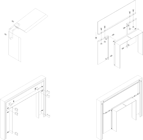
2.5Air control plate, faceplate and fan Assembly Instructions

1.Place the faceplate panels with the finished side down on a flat, soft, non-abrasive surface.

2.Assemble the faceplate trim, attaching the mitered corners with the corner brackets. (see Figure 2.4)

3.Line up the holes of the side and top panels and secure with the screws, washers and nuts. (see Figure 2.5a)

4.Slide the assembled trim over the edges of the faceplate.

5.Secure trim to faceplate using "U" shaped clips. (see Figure 2.5b)

Figure 2.4

Figure 2.5a

Figure 2.5b

Figure 2.5c

6.Fan is already attached to the unit at the factory with two tie straps. Remove the two tie straps and clip the blower assembly back onto the unit.

Section 3.0 Operation

10

Image 11
Contents Escape 1400-I Insert Introduction Table of Contents Escape 1400-I Dimensions Masonry & Zero Clearance Requirements Pre-Installation RequirementsVenting Requirements Clearances To Combustibles Measured From Insert Body InstallationHearth Requirements Suitable Fireplace DimensionsSafety Information Installation Instructions Operation Air control plate, faceplate and fan Assembly InstructionsSafety Information Fuel Lighting a Fire Simple Wood Moisture TestDraft Settings Fan Operation Maintaining The FireAsh Removal MaintenanceCare And Cleaning Glass Cleaning and maintenanceCreosote Formation And Need For Removal Chimney CleaningBaffle installation & removal for Escape Baffle Installation for EscapeImportant Notes Secondary Air Tube ReplacementRemoval instructions Secondary Air Tube replacement Fan Maintenance & CareEscape 1400-I Insert Model SpecificationsDrolet Limited Lifetime Warranty