DeLonghi DEBIGE 2440 E, DEBIGE 2440 W, DEBIGE 2440 SS warranty Installation to the Cabinet

Page 23

installation

INSTALLATION TO THE CABINET

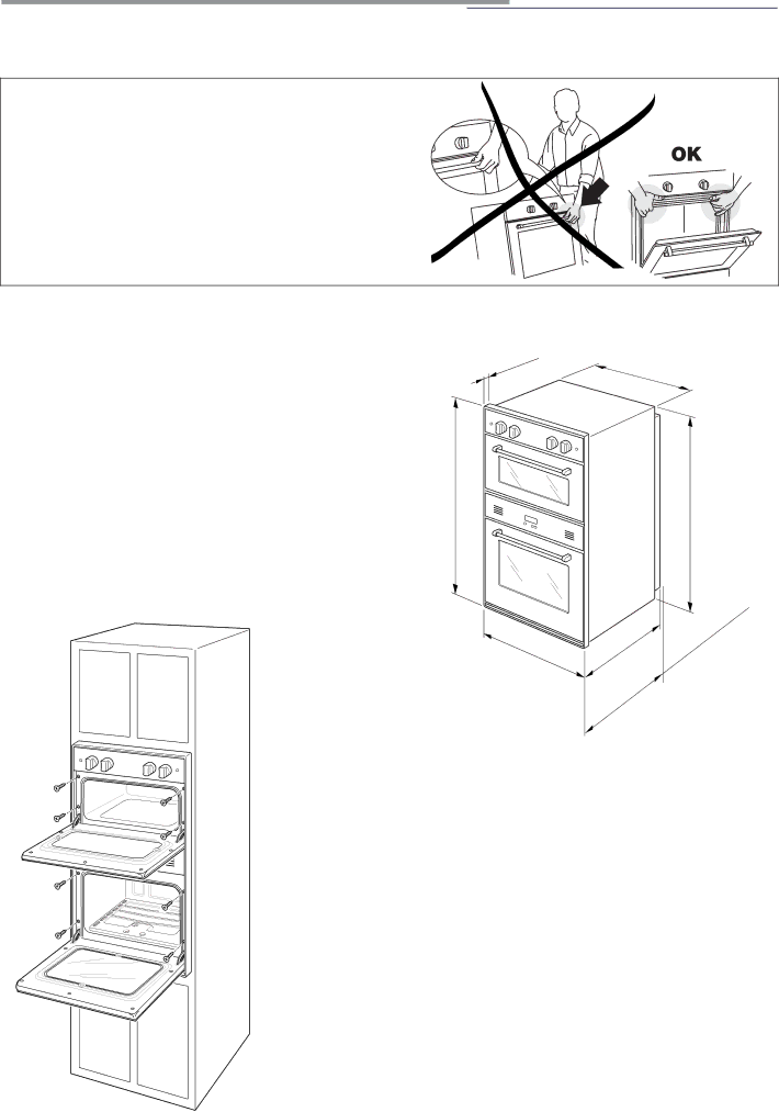
Taking care NOT to lift the oven by the door handle.

This oven may be installed to 24" minimum (609.5 mm) wide cabinets

25/32"


Oven dimensions (fig. 6.1):

(20

mm)


• width =

24" (609.5 mm);


• depth =

21" 3/4 (553 mm);


• depth =

23" 1/4 (590 mm) with gas pressure regulator fitted;


• height = 39"61/64 (1015 mm);


• oven frame depth = 25/32" (20 mm);

39"61/64

(1015mm)

• width = 22" (559 mm);

Cutout dimensions (fig. 6.3):


• depth = 23" (584.2 mm) minimum from front corner of cutout;

• height = 38" (965.5 mm);

24"

(609.


5

mm)


21"

49/64

(553


mm)


37" 13/16

(960.6 mm)


re


ssu


re

d


gas

p


21"

3/4


fitte


mm)

regulator


(553

with


1/4


23"


mm)


(590


Fig. 6.1


IMPORTANT NOTE: THE BOTTOM OF CUTOUT SHALL BE AT LEAST 22" 5/8 (574.4 mm) FROM THE FLOOR.

DO NOT INSTALL THE OVEN BENEATH THE WORK COUNTER.

On the lover side, the oven must lay on a support standing the oven weight. Oven support surface MUST be solid.

All openings in the wall or floor where the oven is to be installed MUST be sealed. Oven location should be away from strong draft areas, such as windows, doors and strong heating vents.

For SAFETY CONSIDERATIONS the oven SHALL BE FASTENED to the cabinet with eight (8) SUITABLE screws (not supplied with the unit) through the holes in the trim (see fig. 6.2). The unit should be lev- eled properly before being secured to the cabinet.

Fig. 6.2

23

Image 23
Contents BUILT-IN Dual Fuel Double Oven What to do if YOU Smell GAS Dear Customer User Instructions Important Precautions and RECOM- MendationsRemove the door before disposal to prevent entrapment Control panels Very Important Notice Electronic Clock fig Electronic clock/end cooking timerElectronic Alarm Setting the Frequency of the Alarm SoundOven Burner How to use the lower gas ovenGeneral Features Using the Oven for the First TimeOven Cooking Ignition of the Oven BurnerOven Light Ignition of the Broil BurnerBroiling Operating Principles How to use the upper electric ovenTemperature Selector Knob fig Using the Oven for the First TimeFunction Selector Knob fig Cooking Different Dishes AT the Same Time SterilizationRegeneration RoastingWrong Ventilated Broiling and BroilingInside of Oven Cleaning and maintenanceGeneral Recomandation Enamelled PartsReplacing the Oven Light Upper Electric Oven Accessories Installation and RemovalLower GAS Oven Accessories Installation and Removal Removing the Oven Doors Door AssemblyOven Doors DO’S and do NOT’S For Your SafetyTools Needed for Installation Installation InstructionsElectrical Grounding Instructions Replacement PartsInstallation to the Cabinet InstallationMaximum Pressure Regulator Gas connectionExplosion Hazard Manual Shut-off Valve figLock Pressure Regulator Installation StepGAS Connection Specification Rigid Pipe Connections Flexible ConnectionsInjectors Table Leak TestingSetting the Pressure Regulator Conversion to LP/PROPANE GASOven burner Adjustment of the Oven Burner Minimum Recommended ground method Electrical connectionLower Oven Upper Oven Electric diagram keyPage Page Code 1102633 ß9