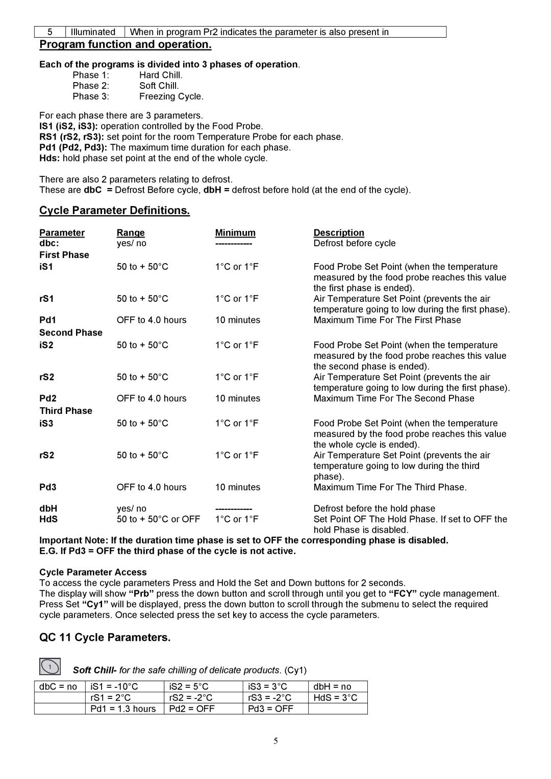
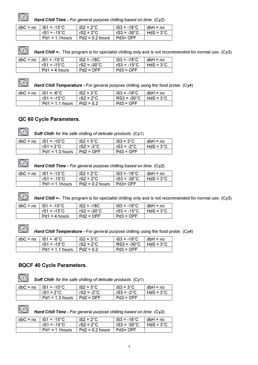
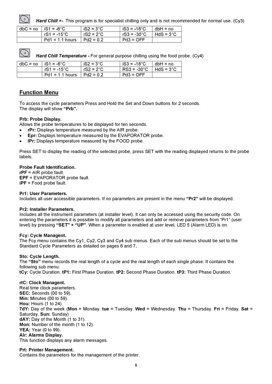
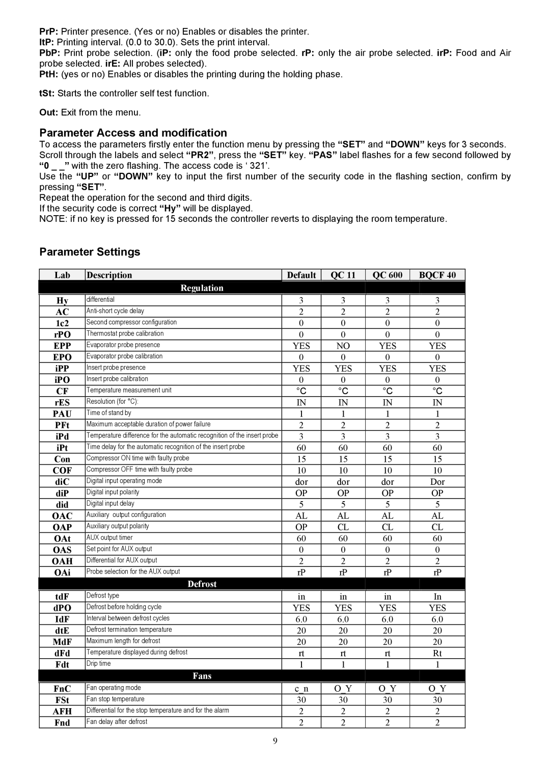
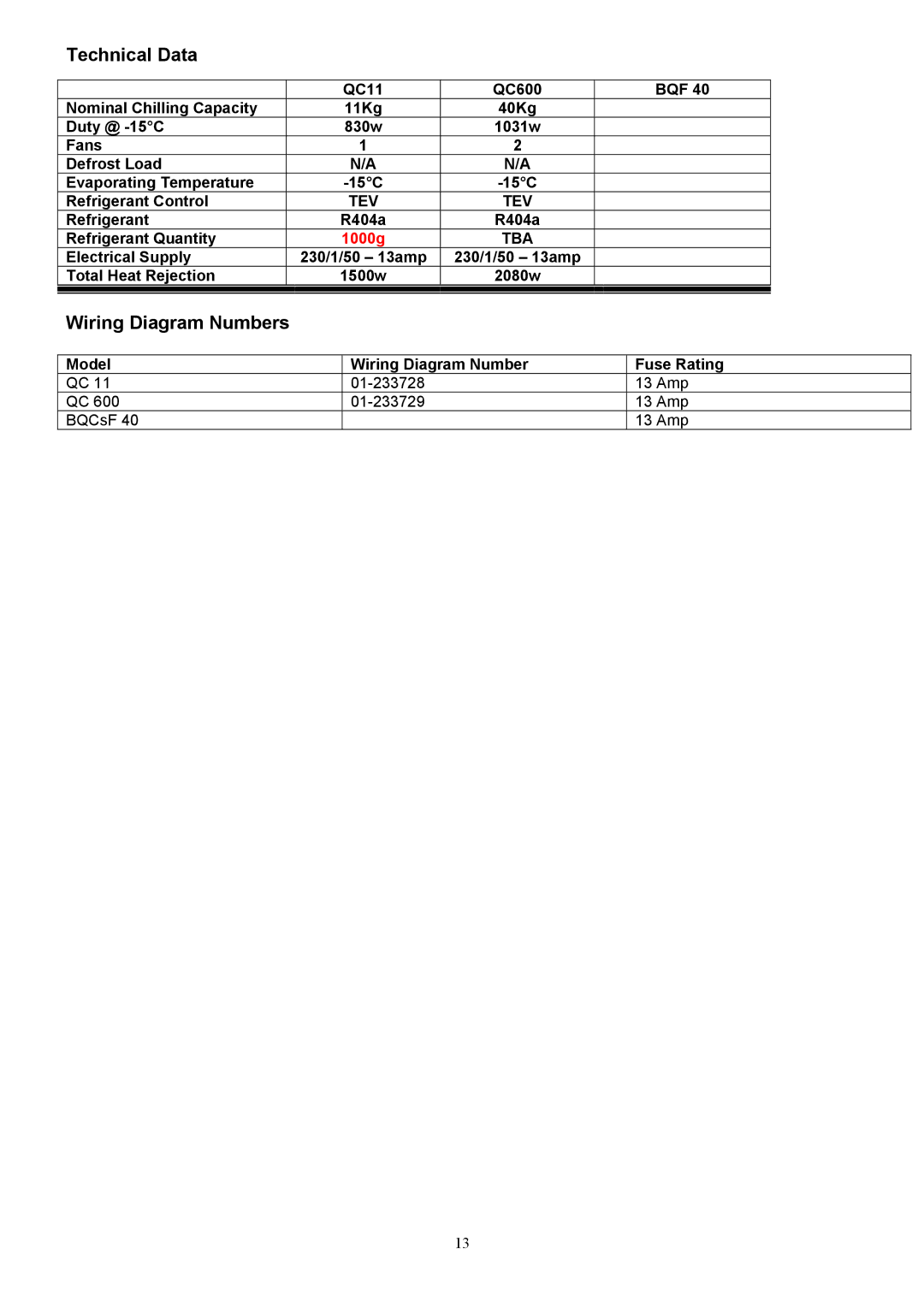
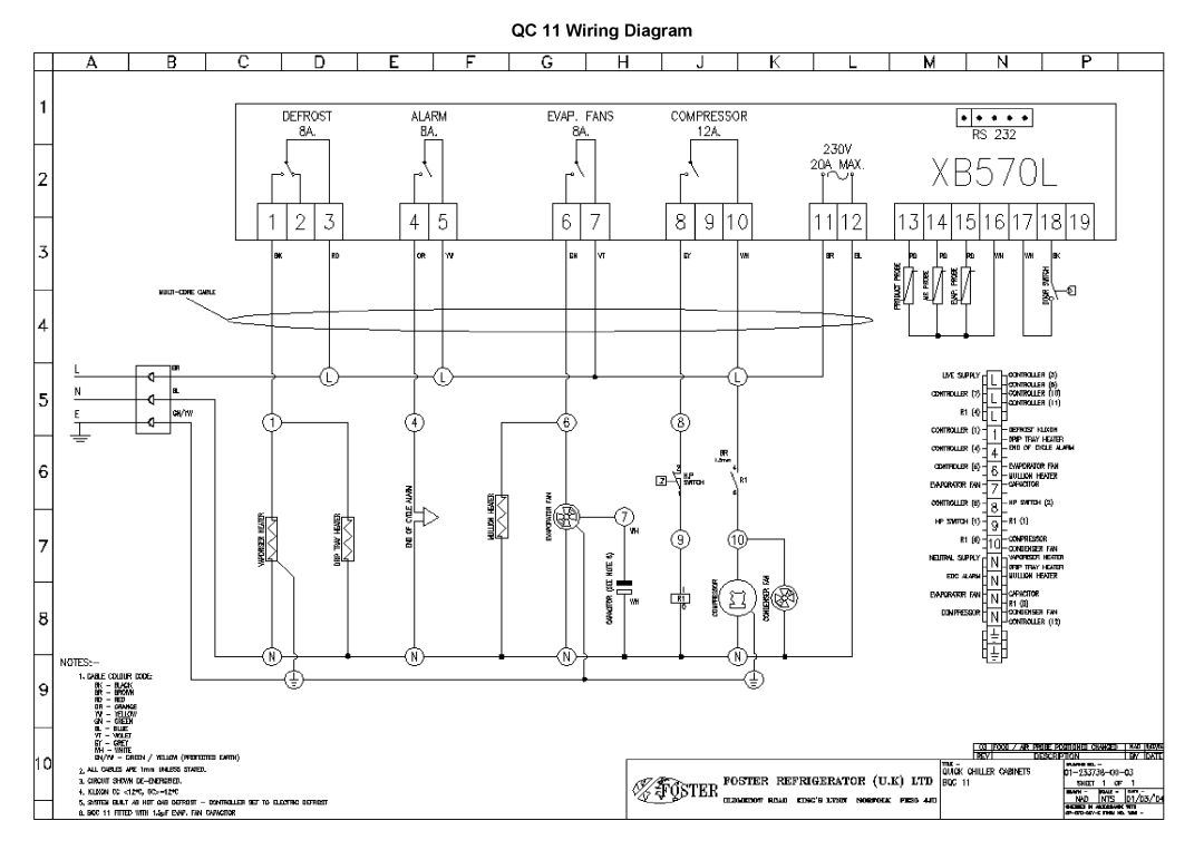
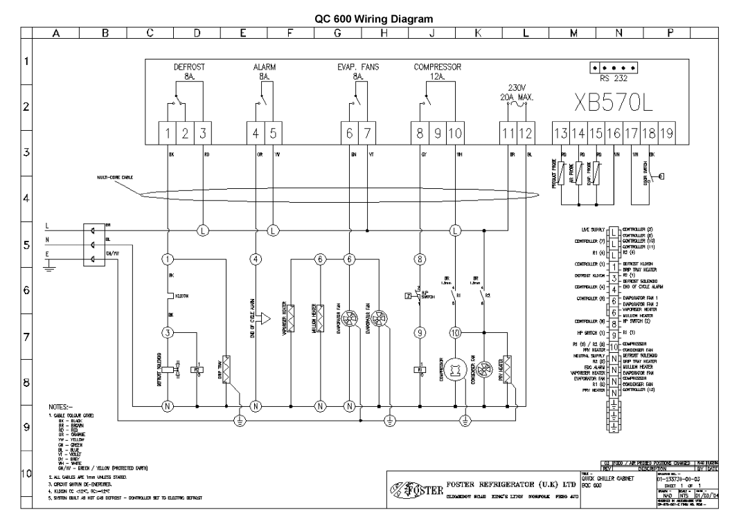
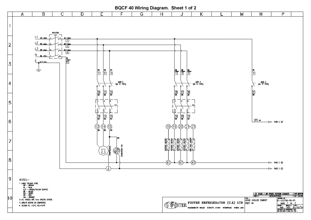
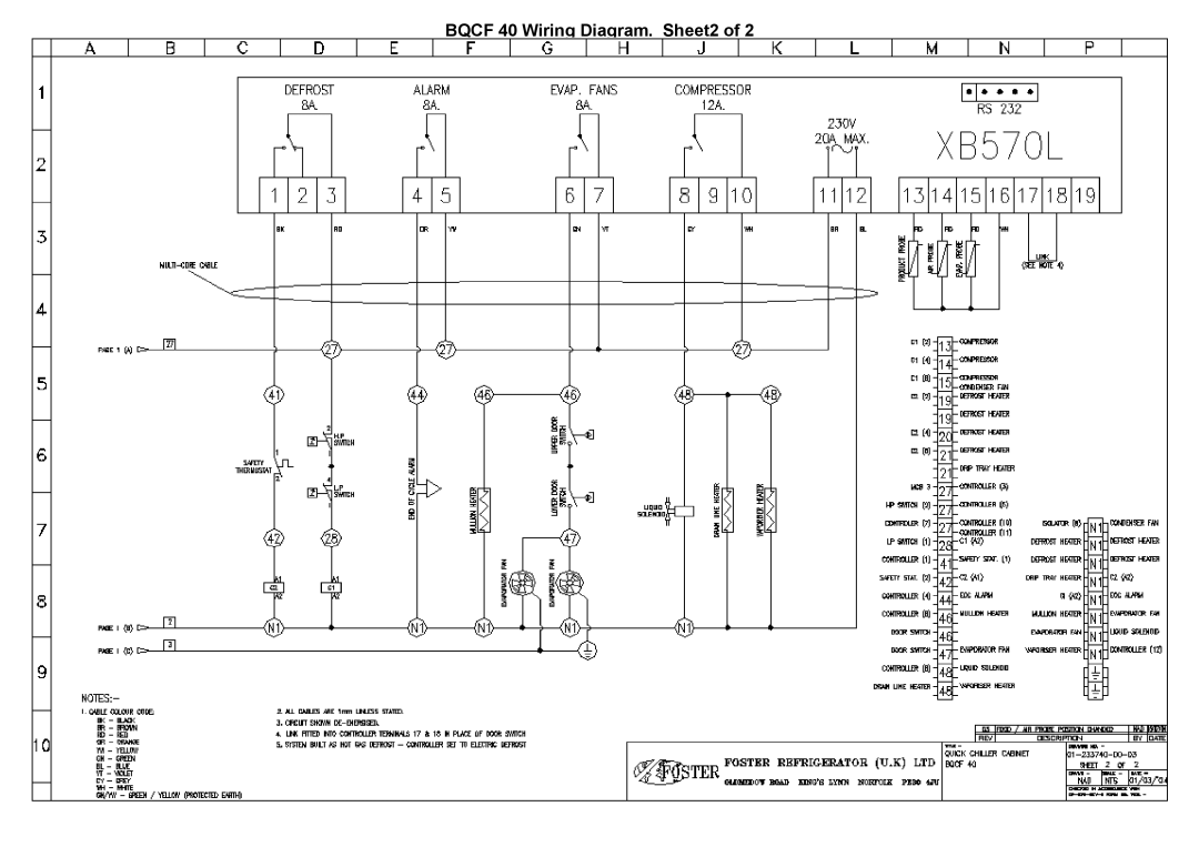
BQCF 40, QC 11, QC 600 specifications
Foster QC 600, QC 11, and BQCF 40 are advanced composite materials widely used across various industries for their unique properties and characteristics. Each of these products serves specific applications, bringing innovations that enhance performance, durability, and overall efficiency.Starting with Foster QC 600, this product is recognized for its superior strength-to-weight ratio, making it an excellent choice for applications where minimizing mass is crucial. QC 600 is often utilized in aerospace and automotive industries, where weight reduction contributes to improved fuel efficiency and performance. The material features exceptional resistance to environmental factors, including UV, moisture, and chemicals, ensuring longevity and sustained application performance. Its unique formulation allows for easy machining and fabrication, providing flexibility in design and assembly.
Next, the Foster QC 11 is particularly noteworthy for its thermal insulation properties. This material is essential in applications requiring effective heat management, such as in industrial ovens, furnaces, and HVAC systems. QC 11 boasts low thermal conductivity, ensuring that heat is maintained where it is needed while preventing unwanted heat transfer. Additionally, it exhibits excellent fire resistance, making it a preferred choice in environments where fire safety is a priority. The ease of installation associated with QC 11 further enhances its usability, allowing for quick adaptations in various setups.
Finally, BQCF 40 stands out for its enhanced impact resistance and durability. This composite material is designed for applications subject to high-stress conditions, such as in construction, marine, and industrial equipment. BQCF 40 showcases outstanding abrasion resistance, making it suitable for environments where wear and tear from mechanical forces is prevalent. Moreover, the composite’s design integrates advanced fiber technology, providing a significant improvement in toughness compared to standard options available on the market. This characteristic ensures the material can withstand heavy loads and impact without compromising integrity.
In summary, Foster QC 600, QC 11, and BQCF 40 represent a cutting-edge collection of materials that cater to diverse industrial needs. With features like lightweight composition, heat insulation, and high impact resistance, these products demonstrate the potential for improved performance and reliability across various applications. Their advanced technologies and unique characteristics make them indispensable in today’s demanding industrial landscape. As industries continue to evolve, integrating such innovative materials will be key to achieving higher standards of performance and efficiency.
