2.2.Receiving and Installation
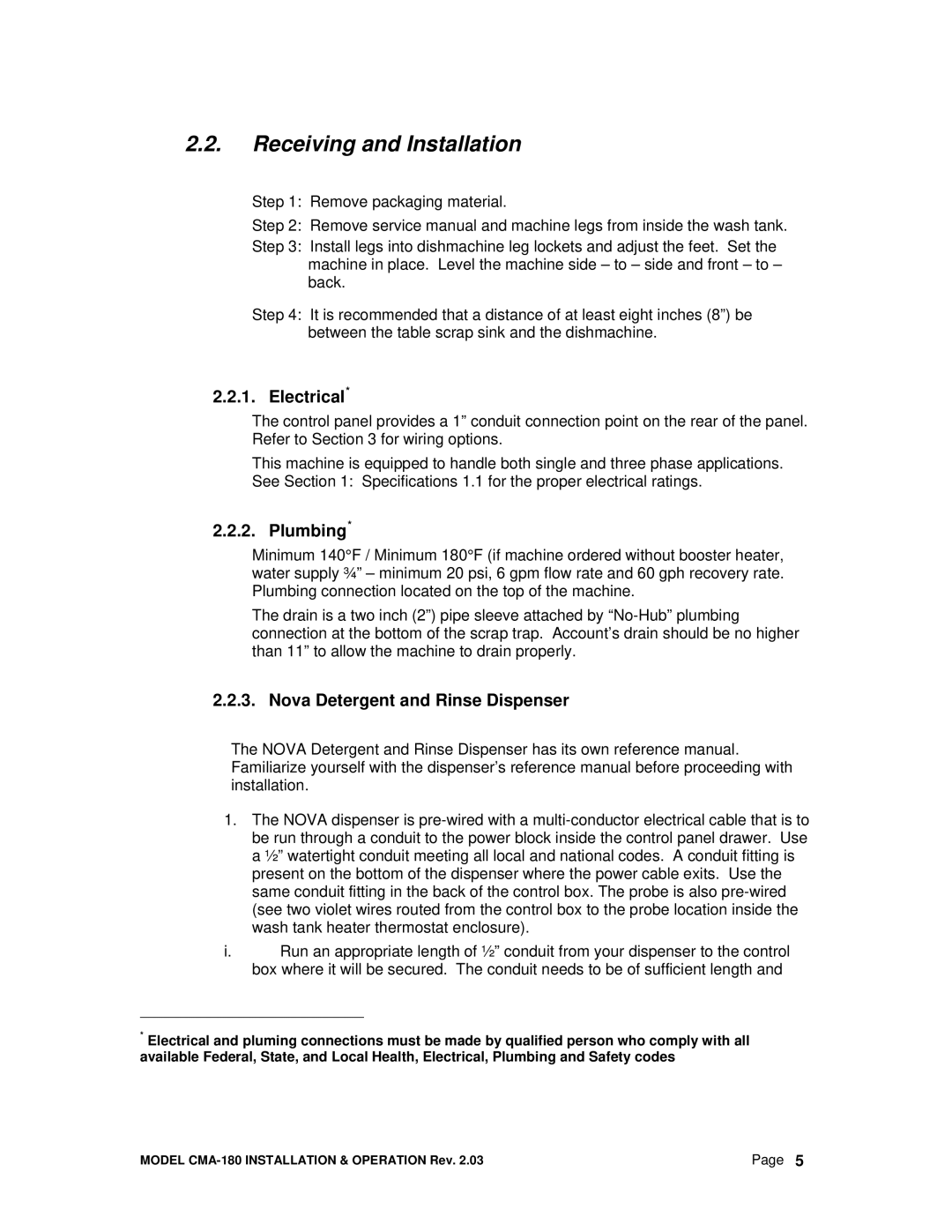
Step 1: Remove packaging material.
Step 2: Remove service manual and machine legs from inside the wash tank.
Step 3: Install legs into dishmachine leg lockets and adjust the feet. Set the machine in place. Level the machine side – to – side and front – to – back.
Step 4: It is recommended that a distance of at least eight inches (8”) be between the table scrap sink and the dishmachine.
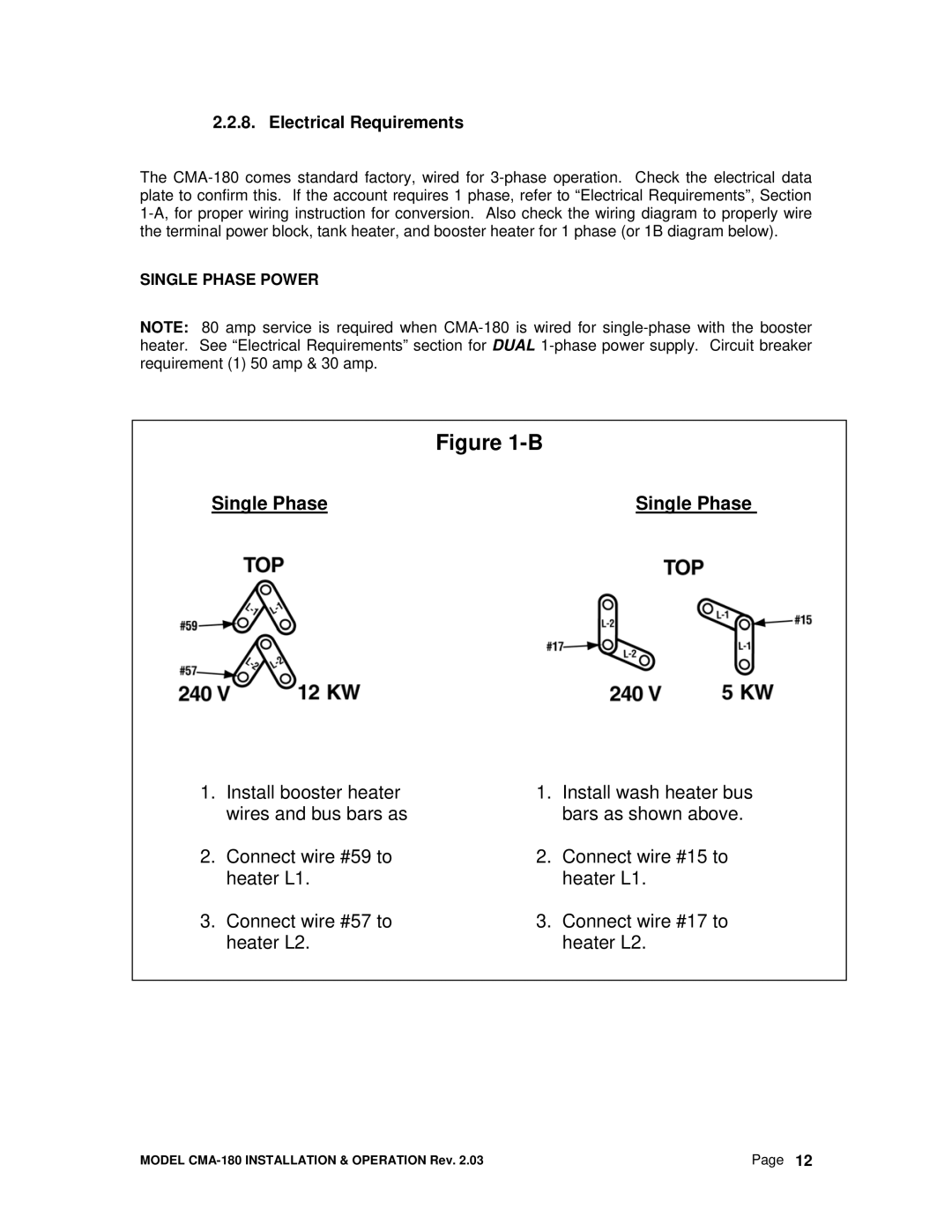
2.2.1. Electrical*
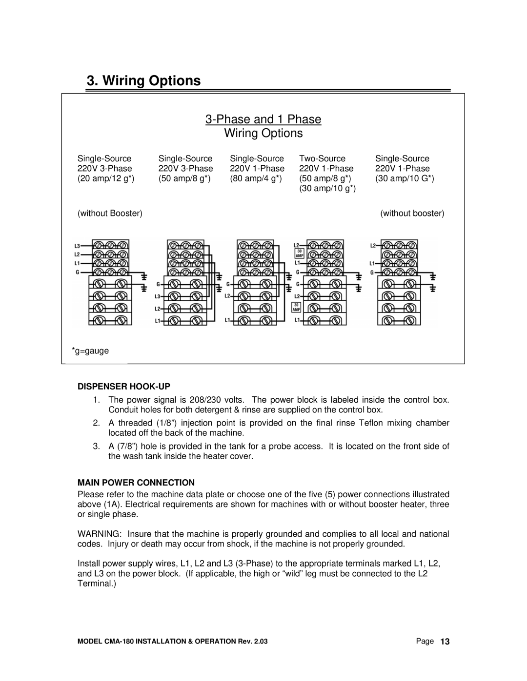
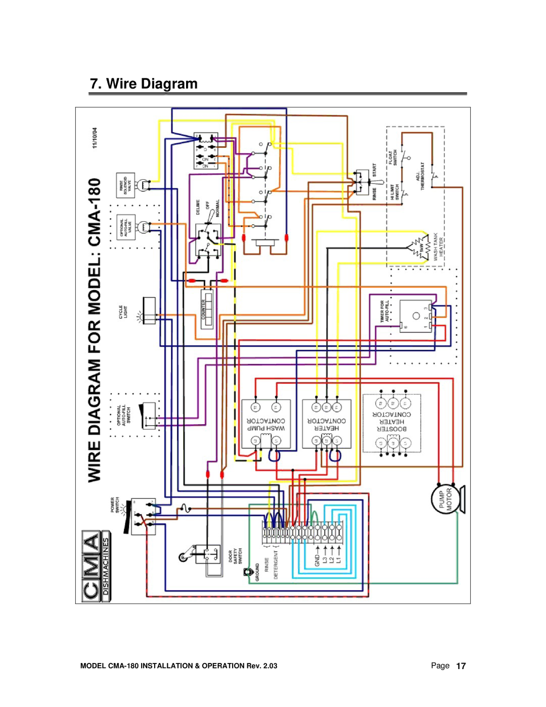
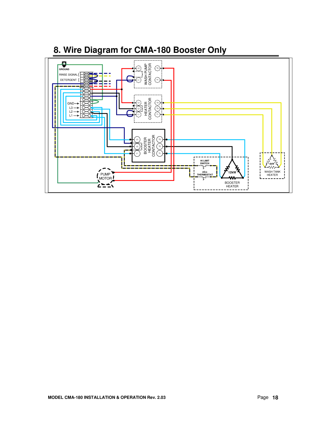
The control panel provides a 1” conduit connection point on the rear of the panel. Refer to Section 3 for wiring options.
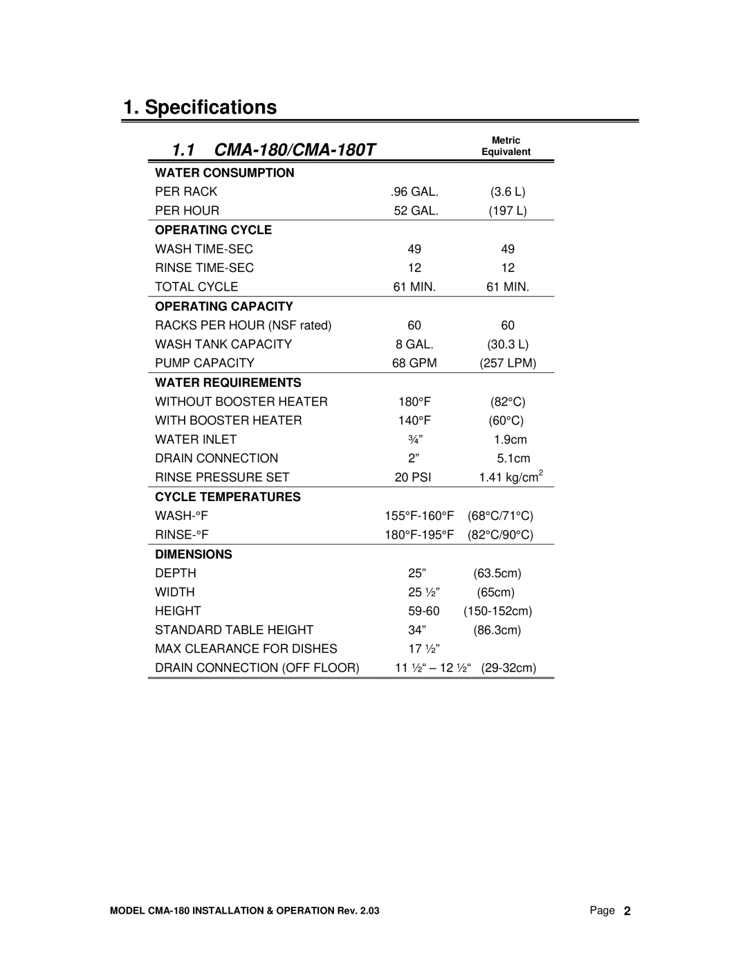
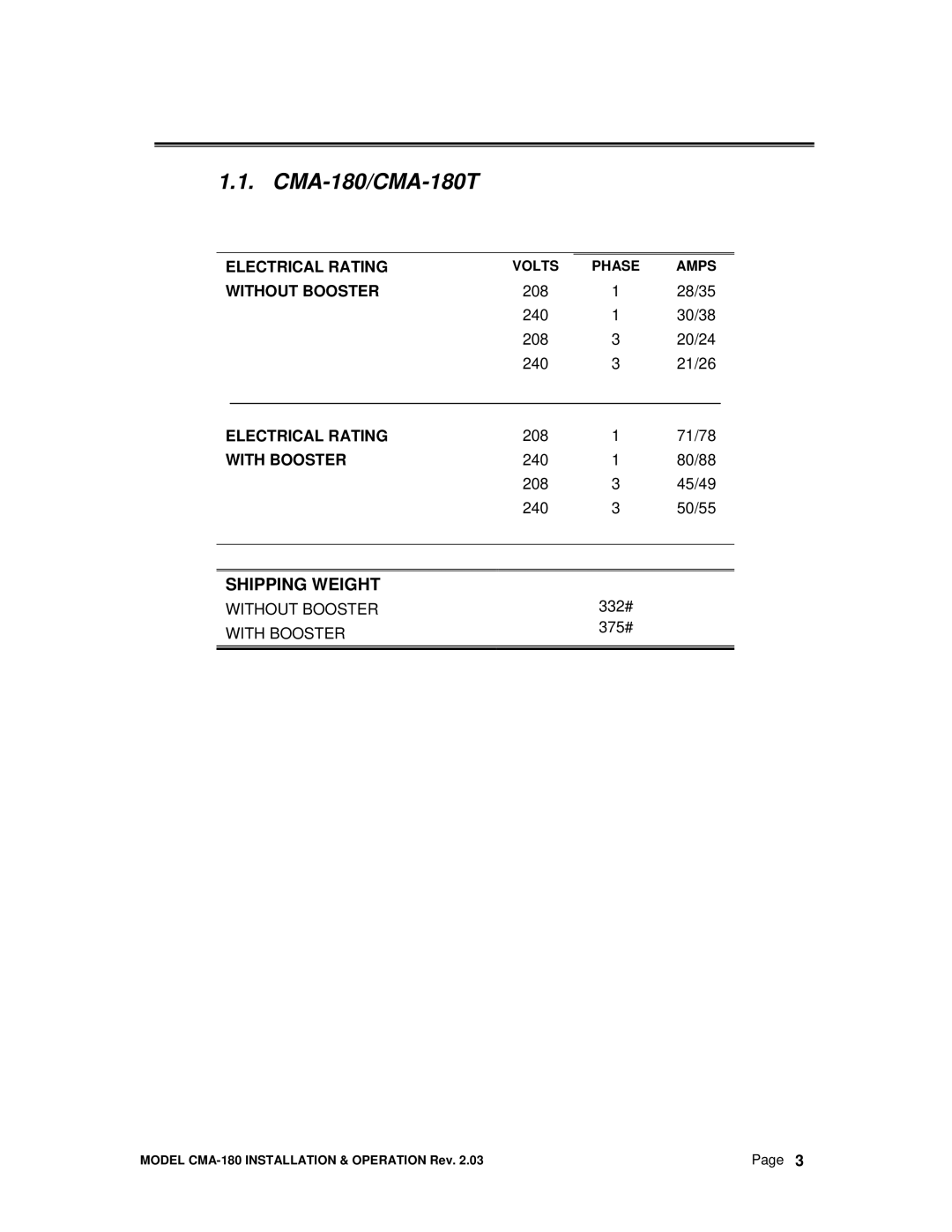
This machine is equipped to handle both single and three phase applications. See Section 1: Specifications 1.1 for the proper electrical ratings.
2.2.2. Plumbing*
Minimum 140°F / Minimum 180°F (if machine ordered without booster heater, water supply ¾” – minimum 20 psi, 6 gpm flow rate and 60 gph recovery rate. Plumbing connection located on the top of the machine.
The drain is a two inch (2”) pipe sleeve attached by
2.2.3. Nova Detergent and Rinse Dispenser
The NOVA Detergent and Rinse Dispenser has its own reference manual. Familiarize yourself with the dispenser’s reference manual before proceeding with installation.
1.The NOVA dispenser is
i.Run an appropriate length of ½” conduit from your dispenser to the control box where it will be secured. The conduit needs to be of sufficient length and
*Electrical and pluming connections must be made by qualified person who comply with all available Federal, State, and Local Health, Electrical, Plumbing and Safety codes
MODEL | Page 5 |
