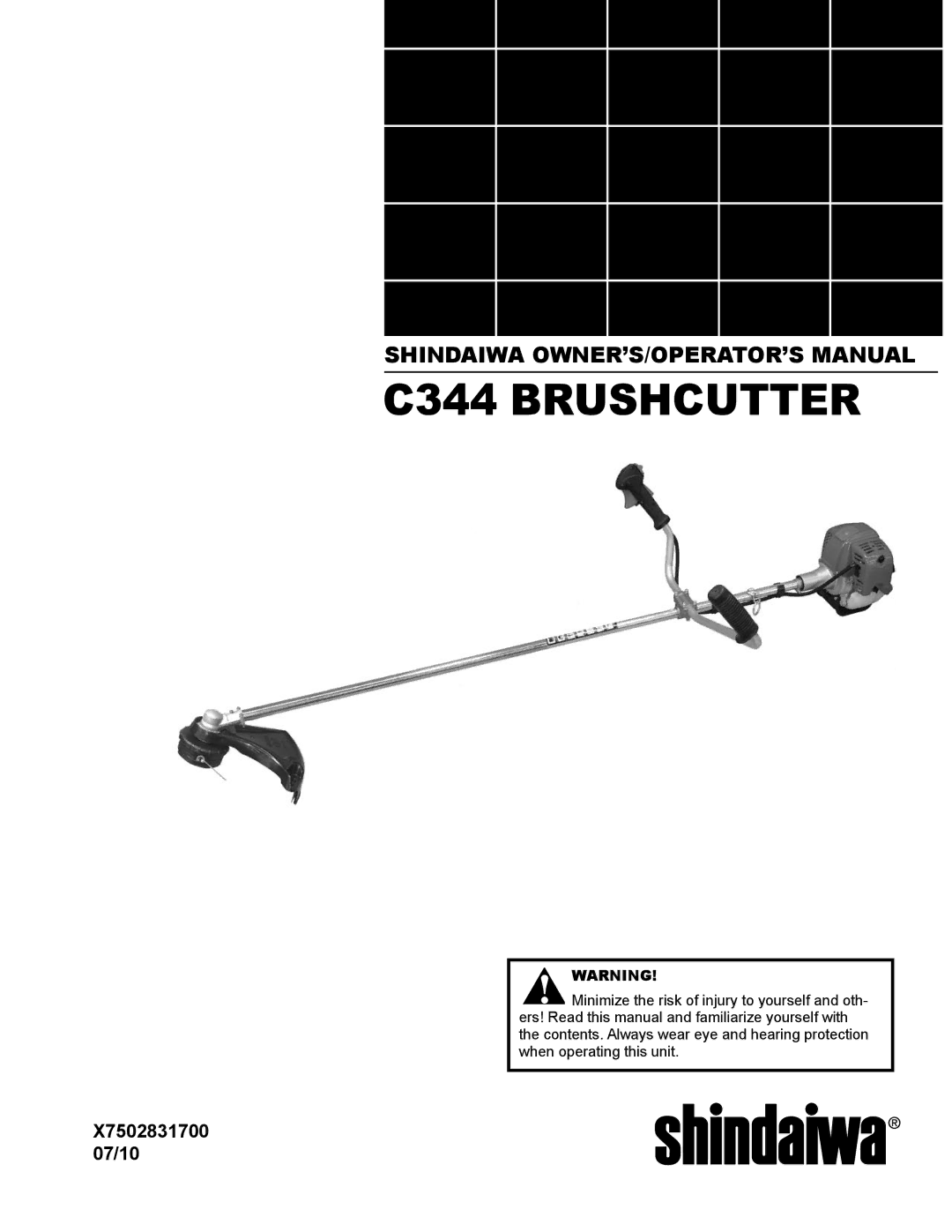
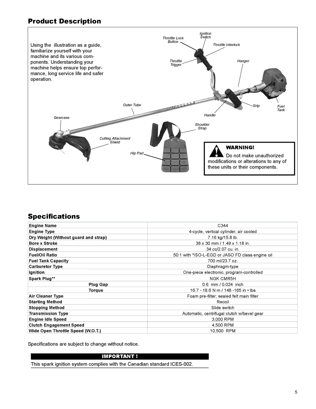
C344, X7502831700 specifications
The Shindaiwa X7502831700, C344 is an exceptional piece of equipment designed for landscaping and forestry professionals who demand reliability and performance. This product is part of Shindaiwa's broad portfolio of high-quality outdoor power tools. It stands out for its robust construction, efficient design, and a range of features that enhance usability and effectiveness.One of the key features of the X7502831700 is its powerful engine, which provides ample torque and power for various applications, from trimming hedges to tackling thick brush. The engine is engineered for efficiency, ensuring that users can complete their tasks without frequent refueling. This not only saves time but also reduces operational costs, making it an ideal choice for professionals who work long hours.
The C344 model incorporates advanced vibration dampening technology. This is crucial for extended use, as it minimizes operator fatigue and maximizes comfort. The ergonomic design of the handle also promotes ease of use, allowing users to maneuver the equipment efficiently without strain. This attention to user experience enhances productivity on the job site.
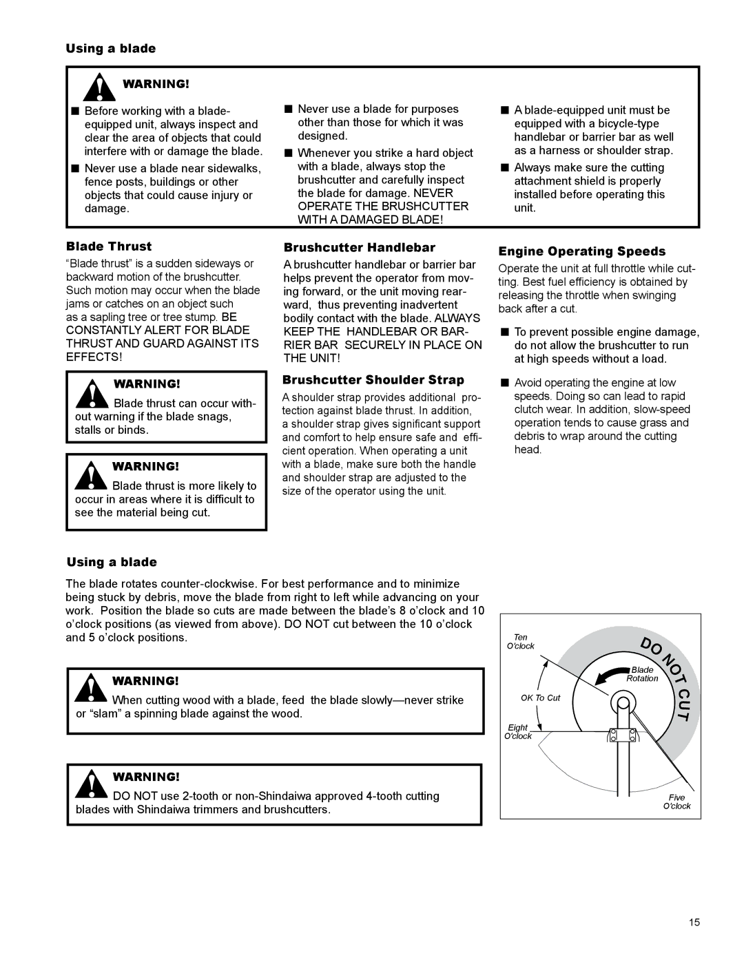
Additionally, the Shindaiwa X7502831700 comes equipped with a high-quality cutting system that ensures precision and clean cuts. The materials used in the construction of the cutting components are durable, designed to withstand the rigors of tough outdoor conditions. This resilience translates to a longer lifespan for the equipment, which is a significant consideration for anyone investing in professional-grade tools.
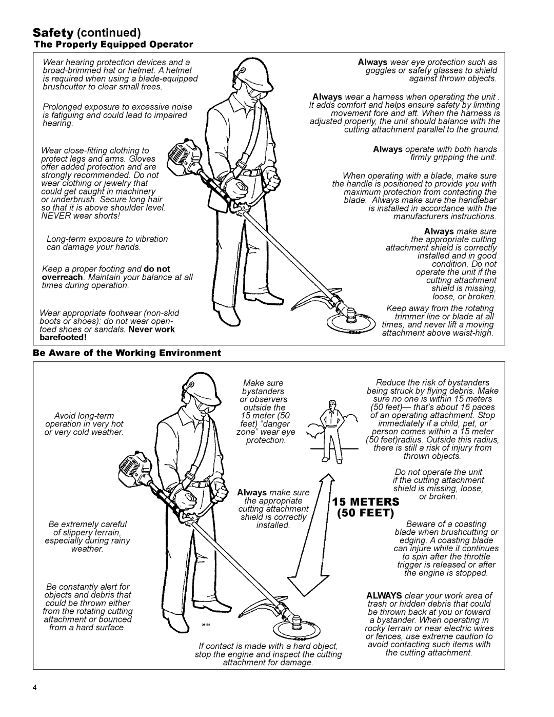
Safety features are another highlight of the C344 model. It includes an easy-start system that reduces the effort required to start the engine, along with protective guards that enhance safety during operation. These features help ensure that users can focus on their tasks with peace of mind.
In conclusion, the Shindaiwa X7502831700, C344 is a powerful and reliable tool that meets the needs of demanding professionals in landscaping and forestry. With its robust engine, ergonomic design, advanced vibration dampening technology, and high-quality cutting system, it stands out as a preferred choice for those seeking performance and durability in their outdoor power tools. Whether you are a professional landscaper or a serious hobbyist, the C344 can help you achieve outstanding results in your outdoor projects.
