5
083048
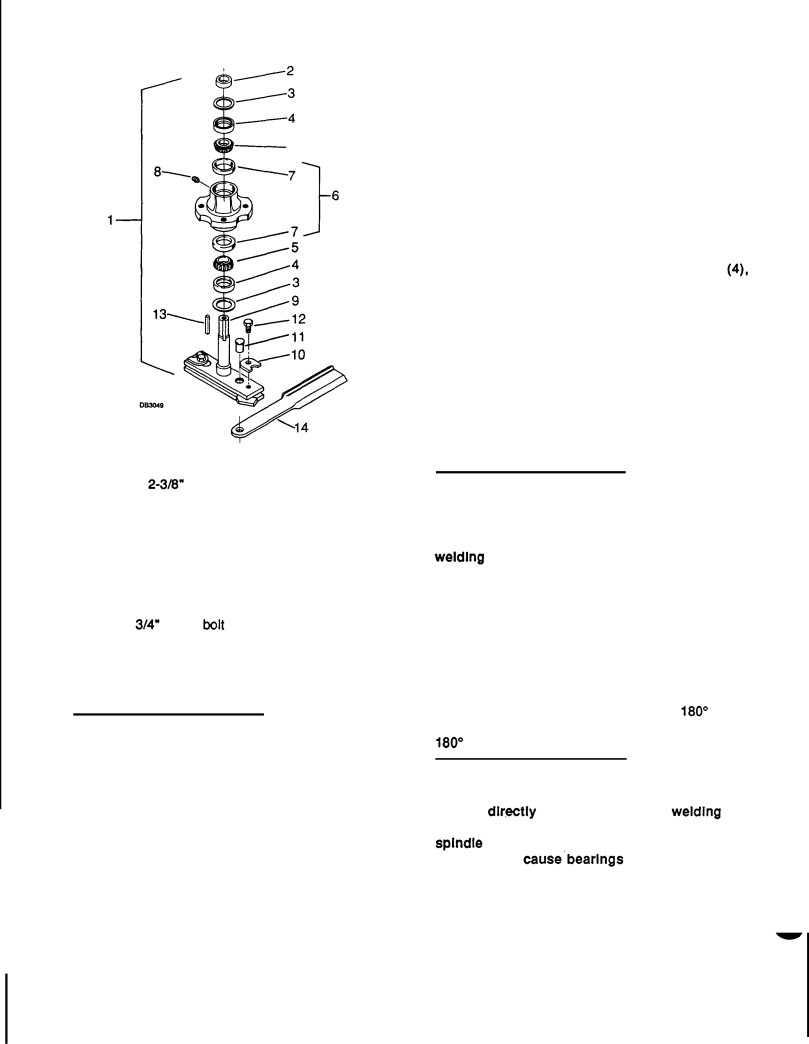
1.Blade spindle
2.Sleeve
3.
4.Seal
5.Bearing cone
6. Spindle housing with cups
7.Bearing cup
8.Grease fitting
9.Spindle shaft and crossbar
10.Blade pin retainer washer
11.QD Blade pin
12.1/2 x 3/4" Nylok bolt
13.Key
14.Blade
Flgure 16. Blade Spindle Assembly
 I IMPORTANT NOTICE
  I
I
Improper positioning of seals can cause seal fallure.
Proper seal installation is important. An improperly installed seal will leak and could cause bearing failure.
Coat area of housing where seals seat, lightly with Permatex.
Pull the rubber portion of seal back and locate spring.
Apply a thin coat of lubricant to bottom seal and install with spring up toward center of housing.
Place seal squarely on housing. Select a piece of pipe or tubing with an outside diameter that will set on outside edge of seal. A tube that is too small will bow seal cage.
Carefully press seal into housing, preventing distortion to metal seal cage. Seal should seat firmly and squarely against machined shoulder in housing.
Make sure seal lip did not roll under. Distortion to seal cage or damage to seal lip will cause seal to leak. Damaged seals must be replaced.
Place bottom washer (3) on shaft and crossbar (9). Place housing assembly with bottom seal (4), bottom cone (5) and cup (7) installedover shaft and crossbar (9). Carefully guide seal over shaft and press shaft into housing.
Fill housing cavity with a medium grade grease. Place top bearing cone (5) and sleeve (2) on shaft.
Press sleeve and bearing onto shaft until all bearing free play is removed and there is a slight drag (similar to adjusting the front wheel bearings on an automobile). Check by spinning spindle. It should turn freely.
 I IMPORTANT NOTICE
  1
1
Bearing adjustment Is set by pressing sleeve agalnst bearing until proper adjustment is attained. Adjustment is maintained by tack weldlng sleeve (2) and washers (3) to spindle shaft.
Be careful not to
Should you
Place a damp rag over bearings to protect them. Tack weld sleeve to shaft in two spots 180' apart. Also tack weld top and bottom washers in two spots
180" apart.
 [ IMPORTANT NOTICE
  I
I
When welding bottom washer, connect welder ground dlcectiy to crossbar. When weldlng top washer and sleeve, connect welder to top of splndle shaft. Failure to connect welder ground properly can cause.bearlngsto become welded to shaft.
Install top seal with spring up away from center of | - | |
housing. Top seal should be flush with, | to 1/16 | |
above, housing. |
| |
22 |