Exmark Vh3615ka, Vh4815ka manual Operation Instructions, Drive LEVER, Neutral Lock Latch Operation

Page 17

4.OPERATION INSTRUCTIONS

4.1Controls

4.1.1Operator Presence Control (OPC) Levers: Located on the upper handle assembly directly above the handle grips. When these levers are depressed, the OPC system senses that the operator is in the normal operator's position. When the levers are released, the OPC system senses that the operator has moved from the normal operating position and will kill the engine if either the speed control lever is not in the neutral position or the blade clutch is engaged.

4.1.2Speed Control Lever: Located in middle of control console, it controls the maximum forward speed and is infinitely variable from neutral (0 mph) to 6.2 mph.

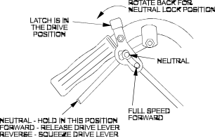
4.1.3Drive Levers: Located on each side of the upper handle assembly directly below the handle grips (See Figure 5). These levers individually control the speed and direction of each drive wheel. When the speed control lever is moved out of the neutral position and the neutral lock latches are moved into the drive position, as shown in Figure 5, and the drive levers are released, the drive wheels are engaged in the forward direction.

Squeezing the left hand and/or right hand lever causes the left hand and/or right hand drive wheel respectively to slow down, stop, or reverse, depending on how far each drive lever is "squeezed". Squeezing the drive levers beyond the neutral position causes the drive wheels to engage in the reverse direction regardless of the position of the neutral lock latches and the speed control lever.

4.1.4Neutral Lock Latch: Located directly above the drive levers. These latches allow the operator to lock the drive levers in a "neutral" position where neither of the drive wheels are engaged in either a forward or reverse direction (See Figure 5).

FIG. 5

DRIVE LEVER, NEUTRAL LOCK LATCH OPERATION

4.1.5Blade Engagement: The “push/pull” blade engagement knob is located on the left side of the control console. To engage the blades, the knob must be pulled toward the operator until the turnbuckle (attached to the blade engagement idler) locks over-center. To disengage the blades, push the knob down until the assist arm contacts the pin on the deck.

4.1.6Throttle-Choke Control: The throttle-choke control lever is located on the control console right side. Choke aids in starting a cold engine. The choke control is a part of the throttle control and activates by moving the throttle control lever to the full forward position. You will notice a detent at the “full throttle” position (approximately 3/4” from top of slot) continue pushing forward into the “choke” position.

- 12 -

Image 17
Contents Page Potential Hazard Exmark Parts PLUS Program Operators Manual Specifications SafetyAssembly Instructions Maintenance & AdjustmentsYour Safety is Involved SafetySafety Alert Symbol TrainingPotential Hazard Operation Maintenance and Storage Riding Attachments Safety SignsPage Specifications Tires DimensionsWheel Drive System Upper Handle Mounting Assembly InstructionsTorque Requirements Hydro Control Linkage Swivel & Drive Linkage Swivel HP Kawasaki Speed Control Throttle Cable HOOK-UPDrive Linkage to Drive Lever Drive LEVER, Neutral Lock Latch Operation Operation InstructionsPre-Start Operating Instructions Potential Hazard Rotating blades under the mower deck are dangerous Transporting Maintenance & AdjustmentsDo not Overfill Periodic MaintenanceMust stop Blade Bolt InstallationService Interval After First 250 hrs, then yearly thereafter Charge Pump Location Fitting Initial Quantity Service Locations Pumps Interval Grease Lubrication ChartPivot Point Spray Lubricant ChartAdjustments Potential Hazard Axle NO. of Spacers Number of 1/4 Blade Spacers Position Cutting Height Adjustment 1 to 4 1/4Blade Engagement Linkage Blade Brake Adjustment Cutter Deck Belt AdjustmentBelt Guide Location Neutral Safety Switch AdjustmentHydro Control LINK/SWIVEL Adjustment Hydro Drive Linkage AdjustmentDrive Lever and Latch in Neutral Position Blades do not Stop When Disengaged Trouble ShootingMower Tracks to Left or Right Mower Cuts UnevenlyEngine Troubleshooting Table Engine TroubleshootingProblem Mower Deck Belt RoutingWiring Diagram Hydraulic Diagram Warranty Page Fold Along Appropriate Line See EXMARK’S Complete Line of Products for Turf Care