PCI Interrupt Routing Table
Slot or Device
Bus#
AMD8111
AMD8131
|
| A | B | C | D | A | B | C | D |
AGP SLOT | N/A | A | B |
|
|
|
|
|
|
|
|
|
|
|
|
|
|
|
|
PCI Slot #1 (64bit) |
|
|
|
| A | B | C | D | |
|
|
|
|
|
|
|
|
|
|
PCI Slot #2 (64bit) |
|
|
|
| D | A | B | C | |
|
|
|
|
|
|
|
|
|
|
PCI Slot #3 (64bit) |
|
|
|
| B | C | D | A | |
|
|
|
|
|
|
|
|
|
|
PCI Slot #4 (64bit) |
|
|
|
| C | D | A | B | |
|
|
|
|
|
|
|
|
|
|
PCI Slot #5 (32bit) | PCI 0 | A | B | C | D |
|
|
|
|
|
|
|
|
|
|
|
|
|
|
Onboard SATA | PCI 0 |
| A |
|
|
|
|
|
|
|
|
|
|
|
|
|
|
| |
Onboard GB LAN |
|
|
|
| A |
|
|
| |
|
|
|
|
|
|
|
|
| |
Onboard FireWire | PCI 0 |
|
|
| A |
|
|
|
|
|
|
|
|
|
|
|
|
| |
IDE |
| A |
|
|
|
|
|
|
|
|
|
|
|
|
|
|
|
|
|
USB |
|
|
|
| A |
|
|
|
|
|
|
|
|
|
|
|
|
| |
AC’97 Audio |
|
| A |
|
|
|
|
|
|
|
|
|
|
|
|
|
|
|
Each row represents one slot or onboard device, each column represents one PCI Interrupt Line. All devices on one column share this line. For standard PCI cards or devices (e.g. those that use only one interrupt) an "A" in a column means that it uses this PCI Interrupt Line. If other cards or devices also use this line, this means the line is shared. According to the PCI specification all cards and devices must support interrupt sharing. Some cards, however, might cause instabilities or performance degradation if they share an interrupt. Try moving those cards to a slot where they won’t share an interrupt.
Some cards may use more than one interrupt. For these cards also take into consideration the small "B" "C" "D" entries in the table.
YOU MUST ALWAYS unplug all three power connectors from the motherboard before ! performing system hardware changes. Otherwise you may damage the board and/or
expansion device.
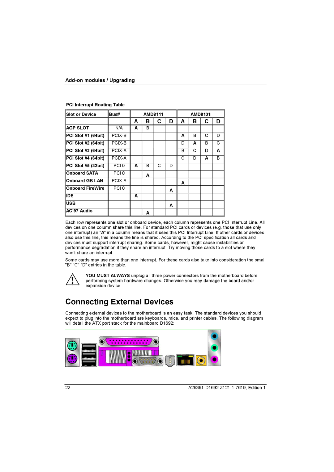
Connecting External Devices
Connecting external devices to the motherboard is an easy task. The standard devices you should expect to plug into the motherboard are keyboards, mice, and printer cables. The following diagram will detail the ATX port stack for the mainboard D1692:
22 |