COREBUILDER® 5000 SWITCHMODULE QUICK START AND REFERENCE | 11 |
12.0Ethernet Backplane SwitchModule Front Panel Features
This section describes the front panel features that are unique to the Ethernet Backplane SwitchModule. See Section 10.0, "Common Front Panel Features" for a description of the PacketChannel LED, Module Status LED, and Reset button.
Ethernet Backplane Port
Status/Activity LEDs
12.1 LEDs
The following table explains the Ethernet Backplane SwitchModule port status or activity LED blink sequences:
Port Status or Activity | Indicates | |
| LED State | |
|
| |
Green | On | Port is enabled and link is OK. |
| Blinking | Link failure or waiting for network |
|
| connection. |
| Off | Port or port functions are disabled. |
Yellow | On | Heavy traffic activity on the port. |
| Blinking | Normal traffic activity on the port. |
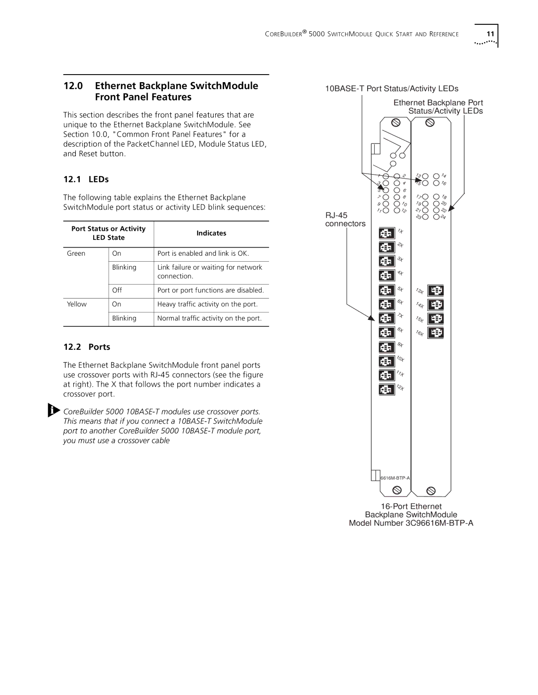
12.2 Ports
The Ethernet Backplane SwitchModule front panel ports use crossover ports with
![]() CoreBuilder 5000
CoreBuilder 5000
1 | 2 | 13 | 14 |
3 | 4 | 15 | 16 |
5 | 6 |
|
|
7 | 8 | 17 | 18 |
9 | 10 | 19 | 20 |
11 | 12 | 21 | 22 |
|
| 23 | 24 |
1X |
![]()
![]()
![]()
![]() 2X
2X
3X |
4X |
5X | 13X |
6X | 14X |
| |
7X | 15X |
| |
8X | 16X |
| |
9X |
|
10X |
|
11X |
|
12X |
|
Backplane SwitchModule
Model Number