COREBUILDER® 5000 SWITCHMODULE QUICK START AND REFERENCE | 13 |
14.0Mixed Technology SwitchModule Front Panel Features
This section describes the Fiber Distributed Date Interface (FDDI) ports and LEDs on the front panel of the following SwitchModules:
■
■
Section 11.0,
14.1 LEDs
FDDI LEDs are green only (not yellow). The following table explains the FDDI port status LED blink sequences and the
LED | State | Indicates |
FDDI Port | Green On | Port is enabled and ring is |
|
| operational. |
| Green | Port is connecting. |
| Blinking |
|
| Off | Port or port functions are |
|
| disabled. |
Green On | Port is enabled and link is OK. | |
| Green | Link failure or waiting for |
| Blinking | network connection. |
| Off | Port or port functions are |
|
| disabled. |
| Yellow | Heavy port traffic activity. |
| On |
|
| Yellow | Normal port traffic activity. |
| Blinking |
|
Green On | Port is enabled and link is OK. | |
| Green | No light on receive fiber. |
| 1 Blink |
|
| Green | Port received jabber. |
| 2 Blinks |
|
| Green | Port is partitioned. |
| 3 Blinks |
|
| Green | Remote fault. |
| 4 Blinks |
|
| Off | Port or port functions are |
|
| disabled. |
| Yellow | Heavy port traffic activity. |
| On |
|
| Yellow | Normal port traffic activity. |
| Blinking |
|
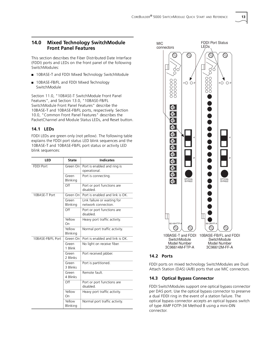
MIC | FDDI Port Status |
connectors | LEDs |
A | B | A | B |
A | A |
B | B |
OPTICAL | OPTICAL |
BYPASS | BYPASS |
SwitchModule SwitchModule
Model Number Model Number
14.2 Ports
FDDI ports on mixed technology SwitchModules are Dual Attach Station (DAS) (A/B) ports that use MIC connectors.
14.3 Optical Bypass Connector
FDDI SwitchModules support one optical bypass connector per DAS port. Use the optical bypass connector to preserve a dual FDDI ring in the event of a station failure. The optical bypass connector accepts an optical bypass switch of type AMP