12COREBUILDER® 5000 SWITCHMODULE QUICK START AND REFERENCE
13.010BASE-FB/FL SwitchModule Front Panel Features
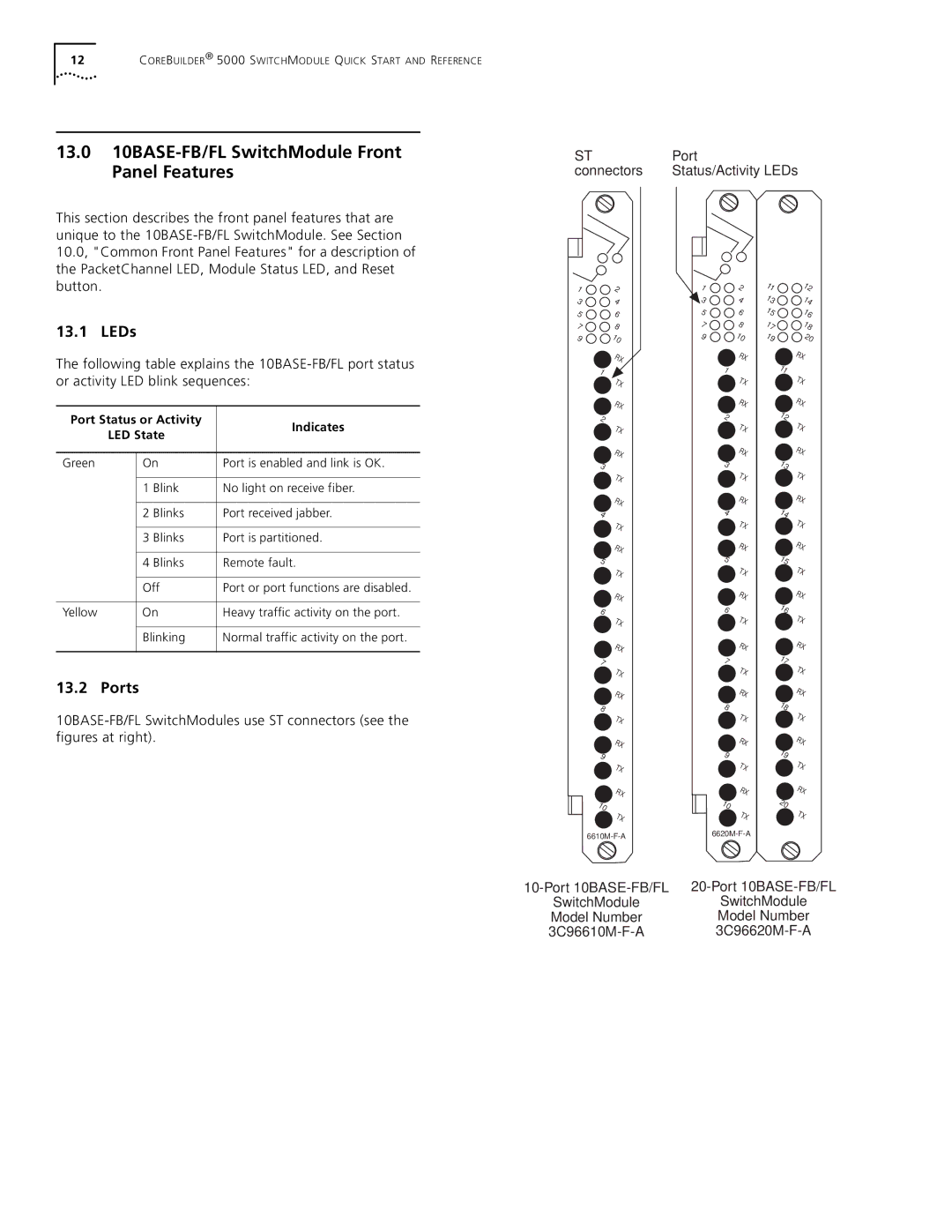
ST | Port |
connectors | Status/Activity LEDs |
This section describes the front panel features that are unique to the
13.1 LEDs
The following table explains the
Port Status or Activity | Indicates | ||
| LED State | ||
|
| ||
Green | On | Port is enabled and link is OK. | |
| 1 | Blink | No light on receive fiber. |
| 2 | Blinks | Port received jabber. |
| 3 | Blinks | Port is partitioned. |
| 4 | Blinks | Remote fault. |
| Off | Port or port functions are disabled. | |
Yellow | On | Heavy traffic activity on the port. | |
| Blinking | Normal traffic activity on the port. | |
13.2 Ports
1![]() 2
2
3![]() 4
4
5 | 6 |
78
9![]() 10
10
![]() RX
RX
1 ![]() TX
TX
![]() RX
RX
2 ![]() TX
TX
RX 3 ![]() TX
TX
RX 4 ![]() TX
TX
RX 5 ![]() TX
TX
![]() RX
RX
6 ![]() TX
TX
![]() RX
RX
7 ![]() TX
TX
![]() RX
RX
8 ![]() TX
TX
![]() RX 9
RX 9 ![]() TX
TX
RX
10 ![]() TX
TX
1![]() 2
2
![]() 3
3 ![]() 4
4
5 | 6 |
78
9![]() 10
10
![]() RX
RX
1 ![]() TX
TX
![]() RX
RX
2 ![]() TX
TX
RX 3 ![]() TX
TX
RX 4 ![]() TX
TX
RX 5 ![]() TX
TX
![]() RX
RX
6 ![]() TX
TX
![]() RX
RX
7 ![]() TX
TX
![]() RX
RX
8 ![]() TX
TX
![]() RX 9
RX 9 ![]() TX
TX
RX
10 ![]() TX
TX
11 13 15
17 19
12 14 16 18 20
RX
11 ![]() TX
TX
RX
12 ![]() TX
TX
![]() RX 13 TX
RX 13 TX
![]() RX 14 TX
RX 14 TX
![]() RX 15 TX
RX 15 TX
![]() RX 16 TX
RX 16 TX
![]() RX 17 TX
RX 17 TX
RX
18 ![]() TX
TX
RX 19 ![]() TX
TX
RX
20 ![]() TX
TX
SwitchModule | SwitchModule |
Model Number | Model Number |