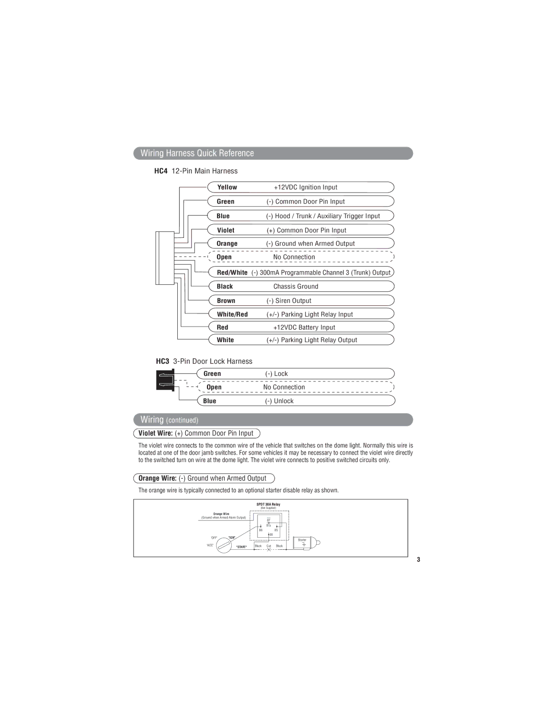
Wiring Harness Quick Reference
HC4 12-Pin Main Harness
|
|
|
| Yellow | +12VDC Ignition Input |
|
|
|
| Green | |
|
|
|
| Blue | |
|
|
|
| Violet | (+) Common Door Pin Input |
|
|
|
| Orange | |
|
|
|
| Open | No Connection |
|
|
|
| Red/White | |
|
|
|
| Black | Chassis Ground |
|
| ||||
|
|
|
| Brown | |
|
|
|
| White/Red | |
|
|
|
| Red | +12VDC Battery Input |
|
|
|
| White | |
HC3 |
| ||||
|
|
|
| Green | |
|
|
|
| ||
|
|
|
| Open | No Connection |
|
|
|
| Blue | |
|
|
|
| ||
Wiring (continued)
Violet Wire: (+) Common Door Pin Input
The violet wire connects to the common wire of the vehicle that switches on the dome light. Normally this wire is located at one of the door jamb switches. For some vehicles it may be necessary to connect the violet wire directly to the switched turn on wire at the dome light. The violet wire connects to positive switched circuits only.
Orange Wire: (-) Ground when Armed Output
The orange wire is typically connected to an optional starter disable relay as shown.
SPDT 30A Relay
(Not Supplied)
Orange Wire
(Ground when Armed Alarm Output)
87
87a
8685
![]() 30
30
"OFF" | "IGN" |
|
| Starter |
|
|
|
| |
"ACC" | "START" | Black | Cut | Black |
|
|
|
|
3