Optional Wiring Diagrams
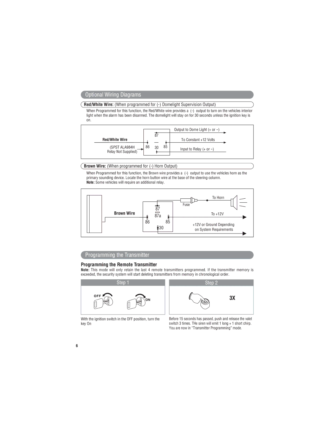
Red/White Wire: (When programmed for
When Programmed for this function, the Red/White wire provides a
Red/White Wire
(SPST ALA984H
Relay Not Supplied)
|
|
|
|
|
| Output to Dome Light (+ or |
|
|
|
|
|
|
| ||
|
| 87 |
|
| To Constant +12 Volts | ||
|
|
|
|
|
| ||
|
|
|
|
|
| ||
|
|
|
|
|
|
|
|
86 | 30 | 85 | Input to Relay (+ or | ||||
|
|
|
|
|
| ||
|
|
|
|
|
|
|
|
|
|
|
|
|
|
|
|
Brown Wire: (When programmed for (-) Horn Output)
When Programmed for this function, the Brown wire provides a
Note: Some vehicles will require an additional relay.
|
|
| To Horn |
| 87 |
| Fuse |
Brown Wire |
|
| |
87a |
| To +12V | |
|
|
| |
86 |
| 85 | +12V or Ground Depending |
| 30 |
| |
|
| on System Requirements | |
|
|
|
Programming the Transmitter
Programming the Remote Transmitter
Note: This mode will only retain the last 4 remote transmitters programmed. If the transmitter memory is exceeded, the security system will start deleting transmitters from memory in chronological order.
Step 1 |
| Step 2 |
3X
With the ignition switch in the OFF position, turn the key On
6
Before 15 seconds has passed, push and release the valet switch 3 times. THe siren will emit 1 long + 1 short chirp. You are now in “Transmitter Programming” mode.