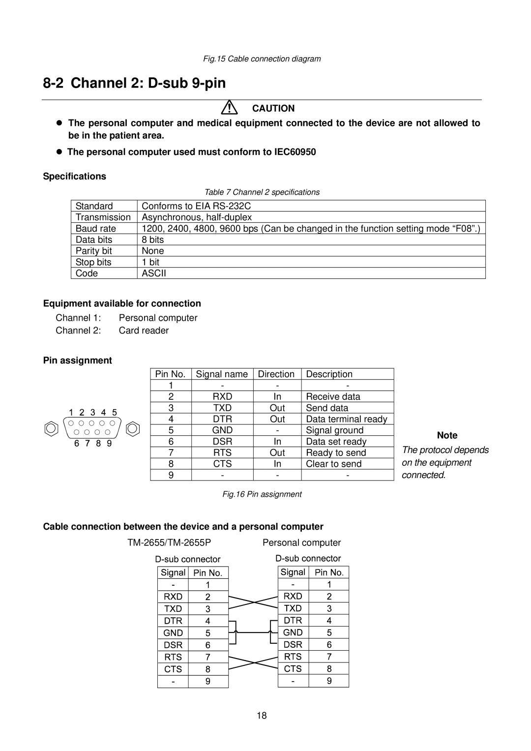
Fig.15 Cable connection diagram
8-2 Channel 2: D-sub 9-pin
CAUTION
zThe personal computer and medical equipment connected to the device are not allowed to be in the patient area.
zThe personal computer used must conform to IEC60950
Specifications
Standard
Transmission
Baud rate
Data bits
Parity bit
Stop bits
Code
Table 7 Channel 2 specifications
Conforms to EIA
1200, 2400, 4800, 9600 bps (Can be changed in the function setting mode “F08”.)
8bits None
1bit
ASCII
Equipment available for connection
Channel 1: Personal computer
Channel 2: Card reader
Pin assignment
Pin No. | Signal name | Direction | Description |
| |
1 | - | - | - |
| |
2 | RXD | In | Receive data |
| |
3 | TXD | Out | Send data |
| |
4 | DTR | Out | Data terminal ready |
| |
5 | GND | - | Signal ground | Note | |
6 | DSR | In | Data set ready | ||
The protocol depends | |||||
7 | RTS | Out | Ready to send | ||
8 | CTS | In | Clear to send | on the equipment | |
9 | - | - | - | connected. |
Fig.16 Pin assignment
Cable connection between the device and a personal computer
|
|
| Personal computer | ||||||||||
|
|
|
|
|
|
|
|
|
|
|
|
|
|
|
|
|
|
|
|
|
|
|
|
|
|
|
|
|
|
|
|
|
|
|
|
|
|
|
|
|
|
|
|
|
|
|
|
|
|
|
|
|
|
|
|
|
|
|
|
|
|
|
|
|
|
|
|
|
|
|
|
|
|
|
|
|
|
|
|
|
|
|
|
|
|
|
|
|
|
|
|
|
|
|
|
|
|
|
|
|
|
|
|
|
|
|
|
|
|
|
|
|
|
|
|
|
|
|
|
|
|
|
|
|
|
|
|
|
|
|
|
|
|
|
|
|
|
|
|
|
|
|
|
|
|
|
|
|
|
|
|
|
|
|
|
|
|
|
|
|
|
|
|
|
|
|
|
|
|
|
|
|
|
|
|
|
|
|
|
|
|
|
|
|
|
|
|
|
|
|
|
|
|
|
|
|
|
|
|
|
|
|
|
|
|
|
|
|
|
|
|
|
|
|
|
|
|
|
|
|
|
|
|
18
