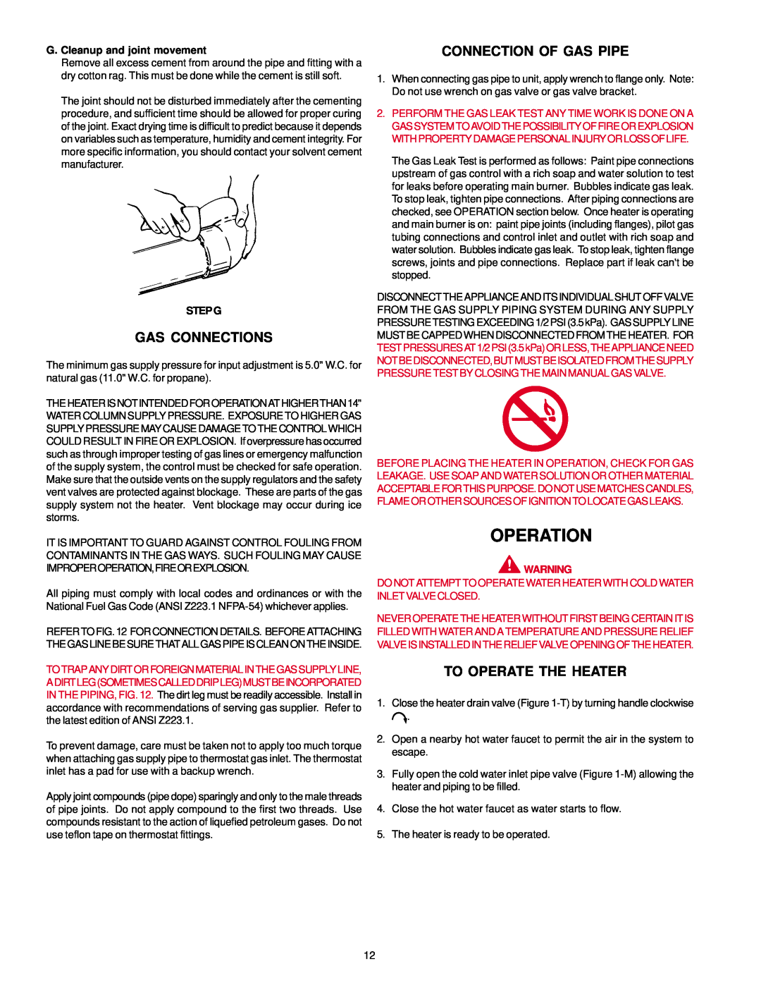
G. Cleanup and joint movement
Remove all excess cement from around the pipe and fitting with a dry cotton rag. This must be done while the cement is still soft.
The joint should not be disturbed immediately after the cementing procedure, and sufficient time should be allowed for proper curing of the joint. Exact drying time is difficult to predict because it depends on variables such as temperature, humidity and cement integrity. For more specific information, you should contact your solvent cement manufacturer.
STEP G
GAS CONNECTIONS
The minimum gas supply pressure for input adjustment is 5.0" W.C. for natural gas (11.0" W.C. for propane).
THEHEATERISNOTINTENDEDFOROPERATIONATHIGHERTHAN14" WATER COLUMN SUPPLY PRESSURE. EXPOSURE TO HIGHER GAS SUPPLY PRESSURE MAY CAUSE DAMAGE TO THE CONTROL WHICH COULD RESULT IN FIRE OR EXPLOSION. If overpressure has occurred such as through improper testing of gas lines or emergency malfunction of the supply system, the control must be checked for safe operation. Make sure that the outside vents on the supply regulators and the safety vent valves are protected against blockage. These are parts of the gas supply system not the heater. Vent blockage may occur during ice storms.
IT IS IMPORTANT TO GUARD AGAINST CONTROL FOULING FROM CONTAMINANTS IN THE GAS WAYS. SUCH FOULING MAY CAUSE IMPROPEROPERATION,FIREOREXPLOSION.
All piping must comply with local codes and ordinances or with the National Fuel Gas Code (ANSI Z223.1
REFER TO FIG. 12 FOR CONNECTION DETAILS. BEFORE ATTACHING THE GAS LINE BE SURE THAT ALL GAS PIPEIS CLEAN ON THE INSIDE.
TOTRAPANYDIRTORFOREIGNMATERIALINTHEGASSUPPLYLINE, ADIRTLEG(SOMETIMESCALLEDDRIPLEG)MUSTBEINCORPORATED IN THE PIPING, FIG. 12. The dirt leg must be readily accessible. Install in accordance with recommendations of serving gas supplier. Refer to the latest edition of ANSI Z223.1.
To prevent damage, care must be taken not to apply too much torque when attaching gas supply pipe to thermostat gas inlet. The thermostat inlet has a pad for use with a backup wrench.
Apply joint compounds (pipe dope) sparingly and only to the male threads of pipe joints. Do not apply compound to the first two threads. Use compounds resistant to the action of liquefied petroleum gases. Do not use teflon tape on thermostat fittings.
CONNECTION OF GAS PIPE
1.When connecting gas pipe to unit, apply wrench to flange only. Note: Do not use wrench on gas valve or gas valve bracket.
2.PERFORM THE GAS LEAK TEST ANY TIME WORK IS DONE ON A GAS SYSTEM TO AVOID THE POSSIBILITY OF FIRE OR EXPLOSION WITHPROPERTY DAMAGE PERSONALINJURY ORLOSS OFLIFE.
The Gas Leak Test is performed as follows: Paint pipe connections upstream of gas control with a rich soap and water solution to test for leaks before operating main burner. Bubbles indicate gas leak. To stop leak, tighten pipe connections. After piping connections are checked, see OPERATION section below. Once heater is operating and main burner is on: paint pipe joints (including flanges), pilot gas tubing connections and control inlet and outlet with rich soap and water solution. Bubbles indicate gas leak. To stop leak, tighten flange screws, joints and pipe connections. Replace part if leak can't be stopped.
DISCONNECT THE APPLIANCE AND ITS INDIVIDUAL SHUT OFF VALVE FROM THE GAS SUPPLY PIPING SYSTEM DURING ANY SUPPLY PRESSURE TESTING EXCEEDING 1/2 PSI (3.5 kPa). GAS SUPPLY LINE MUST BE CAPPED WHEN DISCONNECTED FROM THE HEATER. FOR TESTPRESSURESAT1/2PSI(3.5kPa)ORLESS,THEAPPLIANCENEED NOTBEDISCONNECTED,BUTMUSTBEISOLATEDFROMTHESUPPLY PRESSURE TEST BY CLOSING THE MAIN MANUAL GAS VALVE.
BEFORE PLACING THE HEATER IN OPERATION, CHECK FOR GAS LEAKAGE. USE SOAP AND WATER SOLUTION OR OTHER MATERIAL ACCEPTABLEFORTHISPURPOSE.DONOTUSEMATCHESCANDLES, FLAME OR OTHER SOURCES OF IGNITION TO LOCATE GAS LEAKS.
OPERATION
![]() WARNING
WARNING
DO NOT ATTEMPT TO OPERATE WATER HEATER WITH COLD WATER INLET VALVE CLOSED.
NEVER OPERATE THE HEATER WITHOUT FIRST BEING CERTAIN IT IS FILLED WITH WATER AND A TEMPERATURE AND PRESSURE RELIEF VALVE IS INSTALLED IN THE RELIEF VALVE OPENING OF THE HEATER.
TO OPERATE THE HEATER
1.Close the heater drain valve (Figure ![]() .
.
2.Open a nearby hot water faucet to permit the air in the system to escape.
3.Fully open the cold water inlet pipe valve (Figure
4.Close the hot water faucet as water starts to flow.
5.The heater is ready to be operated.
12