barb, use a wire tie or hose clamp (not supplied with kit) and secure.

6.Take the other end of the flexible tubing and slide it through the hose clamp on the jacket top cover and install it into one of the four barb fittings in vent pipe assembly #2.

7.Once installed along with the rest of the vent configuration, make sure to operate the unit through at least one heat up cycle to ensure there is no leakage around the hose barb or any joints of the VAA or vent pipe system.

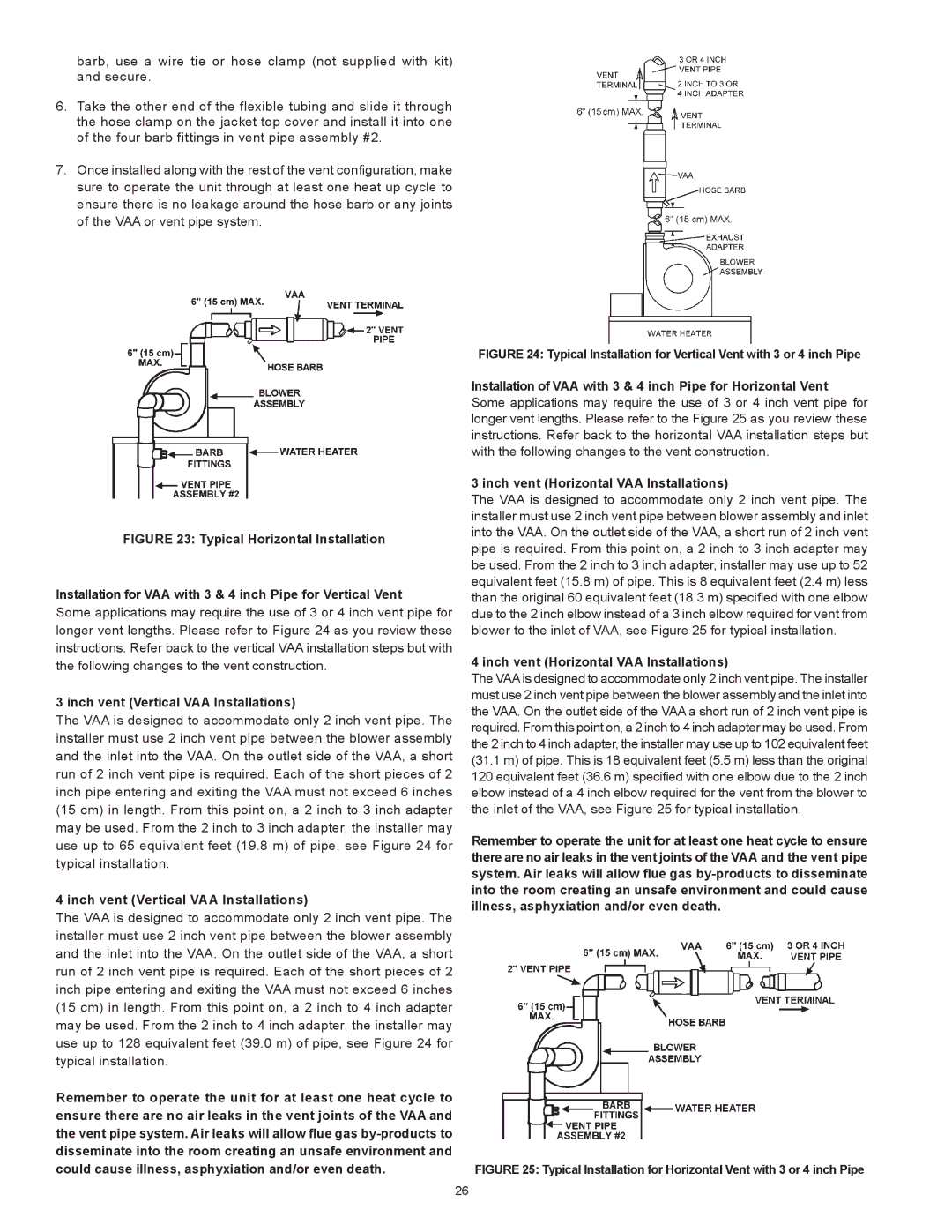
FIGURE 23: Typical Horizontal Installation

Installation for VAA with 3 & 4 inch Pipe for Vertical Vent

Some applications may require the use of 3 or 4 inch vent pipe for longer vent lengths. Please refer to Figure 24 as you review these instructions. Refer back to the vertical VAA installation steps but with the following changes to the vent construction.

3 inch vent (Vertical VAA Installations)

The VAA is designed to accommodate only 2 inch vent pipe. The installer must use 2 inch vent pipe between the blower assembly and the inlet into the VAA. On the outlet side of the VAA, a short run of 2 inch vent pipe is required. Each of the short pieces of 2 inch pipe entering and exiting the VAA must not exceed 6 inches (15 cm) in length. From this point on, a 2 inch to 3 inch adapter may be used. From the 2 inch to 3 inch adapter, the installer may use up to 65 equivalent feet (19.8 m) of pipe, see Figure 24 for typical installation.

4 inch vent (Vertical VAA Installations)

The VAA is designed to accommodate only 2 inch vent pipe. The installer must use 2 inch vent pipe between the blower assembly and the inlet into the VAA. On the outlet side of the VAA, a short run of 2 inch vent pipe is required. Each of the short pieces of 2 inch pipe entering and exiting the VAA must not exceed 6 inches (15 cm) in length. From this point on, a 2 inch to 4 inch adapter may be used. From the 2 inch to 4 inch adapter, the installer may use up to 128 equivalent feet (39.0 m) of pipe, see Figure 24 for typical installation.

Remember to operate the unit for at least one heat cycle to ensure there are no air leaks in the vent joints of the VAA and the vent pipe system. Air leaks will allow flue gas by-products to disseminate into the room creating an unsafe environment and could cause illness, asphyxiation and/or even death.

FIGURE 24: Typical Installation for Vertical Vent with 3 or 4 inch Pipe

Installation of VAA with 3 & 4 inch Pipe for Horizontal Vent Some applications may require the use of 3 or 4 inch vent pipe for longer vent lengths. Please refer to the Figure 25 as you review these instructions. Refer back to the horizontal VAA installation steps but with the following changes to the vent construction.

3 inch vent (Horizontal VAA Installations)

The VAA is designed to accommodate only 2 inch vent pipe. The installer must use 2 inch vent pipe between blower assembly and inlet into the VAA. On the outlet side of the VAA, a short run of 2 inch vent pipe is required. From this point on, a 2 inch to 3 inch adapter may be used. From the 2 inch to 3 inch adapter, installer may use up to 52 equivalent feet (15.8 m) of pipe. This is 8 equivalent feet (2.4 m) less than the original 60 equivalent feet (18.3 m) specified with one elbow due to the 2 inch elbow instead of a 3 inch elbow required for vent from blower to the inlet of VAA, see Figure 25 for typical installation.

4 inch vent (Horizontal VAA Installations)

The VAA is designed to accommodate only 2 inch vent pipe. The installer must use 2 inch vent pipe between the blower assembly and the inlet into the VAA. On the outlet side of the VAA a short run of 2 inch vent pipe is required. From this point on, a 2 inch to 4 inch adapter may be used. From the 2 inch to 4 inch adapter, the installer may use up to 102 equivalent feet (31.1 m) of pipe. This is 18 equivalent feet (5.5 m) less than the original 120 equivalent feet (36.6 m) specified with one elbow due to the 2 inch elbow instead of a 4 inch elbow required for the vent from the blower to the inlet of the VAA, see Figure 25 for typical installation.

Remember to operate the unit for at least one heat cycle to ensure there are no air leaks in the vent joints of the VAA and the vent pipe system. Air leaks will allow flue gas by-products to disseminate into the room creating an unsafe environment and could cause illness, asphyxiation and/or even death.

FIGURE 25: Typical Installation for Horizontal Vent with 3 or 4 inch Pipe

26

Page 26
Image 26
A.O. Smith BTX-80 SERIES 100 instruction manual Inch vent Vertical VAA Installations

BTX-80 SERIES 100 specifications

The A.O. Smith BTX-80 Series 100 is a cutting-edge heating solution designed for effective and efficient water heating. This model is particularly well-suited for residential applications, offering an impressive balance of performance and energy efficiency.

One of the standout features of the BTX-80 Series 100 is its innovative design, which incorporates a high-efficiency condensing technology. This allows the unit to capture and utilize heat that would otherwise be lost in traditional systems, thereby maximizing energy usage and reducing overall operating costs. With an impressive energy factor (EF) rating, this water heater contributes to lower utility bills while promoting environmental sustainability.

The BTX-80 is equipped with a powerful 80-gallon tank, providing ample hot water for households of varying sizes. Its large capacity ensures that multiple appliances can operate simultaneously without running out of hot water, making it an ideal choice for families with high demand. The model also incorporates a robust heating element that ensures rapid recovery and maintains consistent water temperatures.

Safety and convenience are paramount in the design of the BTX-80. It features a comprehensive digital control system that allows users to set precision temperature settings according to their needs. The intuitive interface simplifies adjustments and monitoring, while safety mechanisms like temperature and pressure relief valves provide peace of mind during operation.

A.O. Smith has also prioritized quality and durability in the construction of the BTX-80 Series 100. The tank is made from high-quality materials and comes with a robust enamel coating that resists corrosion and extends its lifespan. Additionally, the unit is backed by a lengthy warranty, reflecting the manufacturer's confidence in its longevity.

Installation and maintenance are straightforward with the BTX-80, as it is designed to fit seamlessly into existing plumbing configurations. Furthermore, the unit operates quietly, ensuring minimal disruption in the home environment.

In conclusion, the A.O. Smith BTX-80 Series 100 stands out in the market as a reliable, energy-efficient, and user-friendly water heating solution. With its advanced technologies and emphasis on safety and durability, it proves to be a smart investment for any household looking to improve their hot water system.