VENT ATTENUATION ASSEMBLY

INSTALLATION INSTRUCTIONS

The Vent Attenuation Assembly (VAA) is designed to provide a reduction in fan noise created in the blower wheel. This installation of this VAA is optional. Review directions thoroughly prior to installing the new VAA. Please contact the manufacturer of the water heater as shown in the instruction manual with any questions or for additional product support.

VENT ATTENUATION ASSEMBLY KIT PARTS LIST

The kit consists of the following items. If a part is missing, use the contact information in the instruction manual to acquire missing component(s).

vent attenuation assembly

flexible tubing

instruction sheet

VENT ATTENUATION ASSEMBLY INSTALLATION

The VAA is designed for both vertical and horizontal installations. The vertical installation and horizontal installations will require that the flexible condensate hose to be attached to the condensate hose barb located on the bottom of the VAA to release condensate. See instructions and diagrams that follow for a more detailed description.

4.Make sure the VAA and vent pipe is supported securely to a permanent fixture (stud or wall). Use standard support straps (not supplied with kit) that may be found at a local hardware store. Failure to properly support the VAA and the surrounding vent pipe could create a hazardous situation. DO NOT puncture any surface of the VAA.

5.Locate flexible tubing. Slide one end of tubing over the hose barb located near end of the VAA. The ridges on the hose barb should prevent the tubing from sliding off, however, to ensure there are no leaks and possible dislocation from hose barb, use a wire tie or hose clamp (not supplied with kit) and secure.

6.Take the other end of the flexible tubing and slide it through the hose clamp on the jacket top cover and install it into one of the four barb fittings in vent pipe assembly #2.

7.Once installed along with the rest of the vent configuration, make sure to operate the unit through at least one heat up cycle to ensure there is no leakage around the hose barb or any joints of the VAA or vent pipe system.

Breathing Hazard - Carbon Monoxide Gas

Do NOT block the holes in the hex plug of vent pipe assembly #1.

Do NOT elevate any portion of the field supplied drain line beyond the 1/2" adaptor above the adaptor. This

must be true for entire length of the drain line including the exit into an appropriate drain.

Condensate lines must be free and clear of debris and must not allow back flow through drain line. Condensate lines must be able to flow freely to an appropriate drain.

Do not allow condensate lines to become crimped closed.

Analyze entire vent system to make sure that condensate will not become trapped in a section of vent pipe and therefore reduce open cross sectional area of vent.

Breathing carbon monoxide can cause brain damage or death.

Always read and understand instruction manual.

Vertical VAA Installations (Recommended)

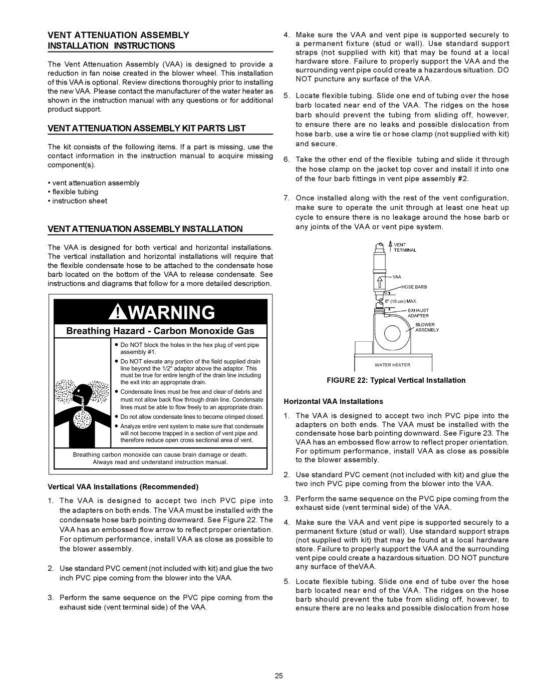
1.The VAA is designed to accept two inch PVC pipe into the adapters on both ends. The VAA must be installed with the condensate hose barb pointing downward. See Figure 22. The

VAA has an embossed flow arrow to reflect proper orientation.

For optimum performance, install VAA as close as possible to the blower assembly.

2.Use standard PVC cement (not included with kit) and glue the two inch PVC pipe coming from the blower into the VAA.

3.Perform the same sequence on the PVC pipe coming from the exhaust side (vent terminal side) of the VAA.

FIGURE 22: Typical Vertical Installation

Horizontal VAA Installations

1.The VAA is designed to accept two inch PVC pipe into the adapters on both ends. The VAA must be installed with the condensate hose barb pointing downward. See Figure 23. The VAA has an embossed flow arrow to reflect proper orientation. For optimum performance, install VAA as close as possible to the blower assembly.

2.Use standard PVC cement (not included with kit) and glue the two inch PVC pipe coming from the blower into the VAA.

3.Perform the same sequence on the PVC pipe coming from the exhaust side (vent terminal side) of the VAA.

4.Make sure the VAA and vent pipe is supported securely to a permanent fixture (stud or wall). Use standard support straps (not supplied with kit) that may be found at a local hardware store. Failure to properly support the VAA and the surrounding vent pipe could create a hazardous situation. DO NOT puncture any surface of theVAA.

5.Locate flexible tubing. Slide one end of tube over the hose barb located near end of the VAA. The ridges on the hose barb should prevent the tube from sliding off, however, to ensure there are no leaks and possible dislocation from hose

25

Page 25
Image 25
A.O. Smith BTX-80 SERIES 100 Vent Attenuation Assembly Installation, Vertical VAA Installations Recommended

BTX-80 SERIES 100 specifications

The A.O. Smith BTX-80 Series 100 is a cutting-edge heating solution designed for effective and efficient water heating. This model is particularly well-suited for residential applications, offering an impressive balance of performance and energy efficiency.

One of the standout features of the BTX-80 Series 100 is its innovative design, which incorporates a high-efficiency condensing technology. This allows the unit to capture and utilize heat that would otherwise be lost in traditional systems, thereby maximizing energy usage and reducing overall operating costs. With an impressive energy factor (EF) rating, this water heater contributes to lower utility bills while promoting environmental sustainability.

The BTX-80 is equipped with a powerful 80-gallon tank, providing ample hot water for households of varying sizes. Its large capacity ensures that multiple appliances can operate simultaneously without running out of hot water, making it an ideal choice for families with high demand. The model also incorporates a robust heating element that ensures rapid recovery and maintains consistent water temperatures.

Safety and convenience are paramount in the design of the BTX-80. It features a comprehensive digital control system that allows users to set precision temperature settings according to their needs. The intuitive interface simplifies adjustments and monitoring, while safety mechanisms like temperature and pressure relief valves provide peace of mind during operation.

A.O. Smith has also prioritized quality and durability in the construction of the BTX-80 Series 100. The tank is made from high-quality materials and comes with a robust enamel coating that resists corrosion and extends its lifespan. Additionally, the unit is backed by a lengthy warranty, reflecting the manufacturer's confidence in its longevity.

Installation and maintenance are straightforward with the BTX-80, as it is designed to fit seamlessly into existing plumbing configurations. Furthermore, the unit operates quietly, ensuring minimal disruption in the home environment.

In conclusion, the A.O. Smith BTX-80 Series 100 stands out in the market as a reliable, energy-efficient, and user-friendly water heating solution. With its advanced technologies and emphasis on safety and durability, it proves to be a smart investment for any household looking to improve their hot water system.