Manuals
/
Acer
/
Computer Equipment
/
Laptop
Acer
4733Z, 4333
manual
Connect the fan cable as shown Chapter
Models:
4333
4733Z
1
105
168
168
Download
168 pages
46.41 Kb
102
103
104
105
106
107
108
109
Specification
Install
System Block Diagram
Bluetooth
Password
Indicators
Wireless and networking
Warranty
Common Problems
Bios Setup Utility
Page 105
Image 105
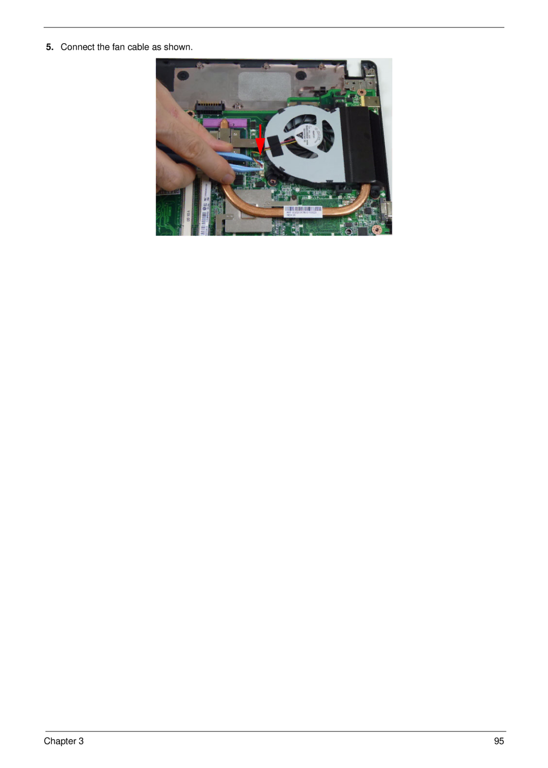
5.
Connect the fan cable as shown.
Chapter 3
95
Page 104
Page 106
Page 105
Image 105
Page 104
Page 106
Contents
Acer Aspire 4333/4733Z Service Guide
Revision History
III
Copyright
Conventions
Preface
Page
Table of Contents
Viii
111
Table of Contents
Table of Contents
Chapter
Features
Dimensions and weight
Wireless and networking
Display
Audio
Power adapter
Power adapter and battery
Battery
Input and control
Optional Items
Software
Environment
Warranty
Penryn
System Block Diagram
Your Acer Notebook tour
Top View
Icon Description
Rear view
Closed Front View
Right View
Left View
Base View
Indicators
Icon Function Description
HDD
Function Left Button Right Button Main Touchpad
Touchpad Basics
Using the Keyboard
Lock Keys and embedded numeric keypad
Lock key Description
Key Description
Windows Keys
Hotkey Icon Function Description
Hot Keys
Hardware Specifications and Configurations
System Board Major Chips Specification
System Memory Specification
VGA
LAN
Pcmcia
Wireless Module 802.11b/g/Draft-N Specification
Memory Combinations Slot Total Memory
0MB
Bluetooth Interface Specification
LAN Interface Specification
3G Module Not available with this model Specification
Speaker Specification
WD WD2500BEVT
Hard Disk Drive Interface Specification
Sata
WD WD3200BPVT-22ZEST0 WD WD5000BEVT-22A0RT0
USB Port Specification
WD7500BPVT-22HXZT1
Ehci
Video Interface Specification
Audio Subsystem Specification
Hdmi Port Specification
Lvds / CRT
Super-Multi Drive Module
Pcmcia Port Not available in this model Specification
DVD-ROM
Plds DS8A4SH
DVD-RW
DVD+RW
Keyboard Controller Specification
DVD-RAM
US & US+ CD-RW
Main Battery Specification Cell
Ports Specification
RTC Battery Specification
AS10D61AH
AUO
External Display Supported Resolution Bits
Card Reader Specification
Camera Specification
System LED Indicator Specification
AC Adapter Specification
Page
Chapter
Navigating the Bios Utility
Bios Setup Utility
Information
Parameter Description
Uuid
Parameter Description Format/Option
Main
Security
Disabled or
Parameter Description Option
Clear or Set
Removing a Password
Setting a Password
Continue
Changing a Password
Boot
PCI LAN
USB HDD
Exit Exit Saving Changes
Exit
Bios Flash Utility
DOS Flash Utility
WinFlash Utility
Remove HDD Password
Remove HDD/BIOS Password Utilities
Removing Bios Passwords
Cleaning Bios Passwords
Using Boot Sequence Selector
Using DMITools
Miscellaneous Utilities
Example 1 Read DMI Information from Memory
Using the LAN MAC Utility
Disassembly Requirements
Machine Disassembly and Replacement
Pre-disassembly Instructions
Main Screw List Quantity Part Number
Disassembly Process
External Modules Disassembly Process
External Modules Disassembly Flowchart
Screw List Step Quantity
Removing the Battery Pack
Removing the SD Dummy Card
Removing the Keyboard
Chapter
Step Size Quantity Screw Type
Removing the ODD Module
Step Size Quantity Screw Type
Main Unit Disassembly Flowchart
Main Unit Disassembly Process
Removing the Lower Cover
Component Overview
Removing the Dimm Modules
Removing the Wlan Module
Removing the USB Board
Remove the one 1 screw from the USB board
Removing the RTC Battery
Removing the Bluetooth Module
Step Size Quantity Screw Type HDD Module M2-0.4*2-I
Removing the HDD Module
Step Size Quantity Screw Type
Removing the LCD Module
Step Size Quantity Screw Type
Removing the Thermal Module
Removing the CPU
Chapter
Removing the Mainboard
Remove the one 1 securing screw from the mainboard
Lift the mainboard away the lower cover Chapter
LCD Module Disassembly Flowchart
LCD Module Disassembly Process
Removing the LCD Bezel
Chapter
Removing the Camera Module
Removing the LCD Panel
Remove the LCD Hinges
Removing the Lvds Cable
Removing the Wlan Antennas
Replacing the Wlan Antennas
LCD Module Assembly Process
Replacing the Lvds Cable
Replacing the LCD Hinges
Removing the LCD Panel
Replace the six 6 securing screws to secure the LCD panel
Replacing the Camera Module
Replacing the LCD Bezel
Page
Replace the two 2 bezel screws
Replacing the Mainboard
Main Unit Assembly Process
Chapter
Replacing the CPU
Replacing the Thermal Module
Connect the fan cable as shown Chapter
Replacing the LCD Module
Page
Replacing the Bluetooth Module
Replacing the HDD Module
100 Chapter
Removing the RTC Battery
Replacing the USB Board
Replacing the Wlan Module
Connect the two 2 antenna cables to the Wlan board as shown
Replacing the Dimm Modules
Replacing the Lower Cover
Replacing the ODD Module
External Module Assembly Process
Replacing the Keyboard
Page
Replacing the SD dummy card
Replacing the Battery Pack
Symptoms Verified Go To
Common Problems
Computer Shutsdown Intermittently
Power On Issue
No Post or Video
No Display Issue
Abnormal Video Display
Random Loss of Bios Settings
Built-In Keyboard Failure
LCD Failure
Internal Speaker Failure
Touchpad Failure
Sound Problems
Microphone Problems
Select Set up microphone
HDD Not Operating Correctly
Select Repair your computer
Select Startup Repair
ODD Not Operating Correctly
ODD Failure
Discs Do Not Play
Drive Not Detected
Thermal Unit Failure
Wireless Function Failure
Other Failures
External Mouse Failure
Intermittent Problems
Undetermined Problems
Dimm
Post Codes
Post Code Range Phase
Peiswitchstack PEI
Peimemoryinstall PEI
Peienterrecoverymode PEI
Peirecoverymediafound PEI
Bdsbeforepciioinstall BDS
Bdsinstallhotkey BDS
Bdsenumerateallbootoption BDS
Dxesmmcontrolerinit DXE
Bdsentersetup BDS
Bdsendofbootselection BDS
Bdsenterbootmanager BDS
Bdsbootdeviceselect BDS
Smmacpienableend SMM
Smmacpienablestart SMM
Smmacpidisablestart SMM
Smmacpidisableend SMM
130 Chapter
Jumper and Connector Locations
Bottom View
CN14 Lvds CN13 RTC CPU CN15 Wlan
CN9/CN10 DDR3
Clearing Password Check and Bios Recovery
Steps for Clearing Bios Password Check
Description Location G2 / G3 Cmos Jumper Dimm bay
Bios Recovery Boot Block
Bios Recovery by Crisis Disk
Bios Recovery Hotkey
Steps for Bios Recovery from USB Storage
FRU Field Replaceable Unit List
Acer Aspire 4333/4733Z Exploded Diagrams
LCD Assembly
Description Acer P/N
Chassis Assembly
ODD
USB FFC
Adapter
Acer Aspire 4333/4733Z FRU List
CASE/COVER/BRACKET Assembly
HDD/HARD Disk Drive
Keyboard
LCD Cover W/ ANT IMR Black
Mainboard
Miscellaneous
Screw List
Chapter 145
Appendix a
Aspire
Model Country Acer Description
Memory
Model Country Acer
China
Aspire 4733Z
LX.R5T0
LX.R8A0
LX.R5T
LX.R8A
SO1GBIII10 SO2GBIII10
Appendix a 150
Appendix B
Bluetooth
Vendor Type Description Adapter
Audio Codec
Vendor Type Description
Camera
Card Reader
Keyboard
Wireless LAN
WiFi Antenna
NB Chipset
SB Chipset
Appendix C
Online Support Information
156
Index
158
Top
Page
Image
Contents