Disassembly Procedure Flowchart
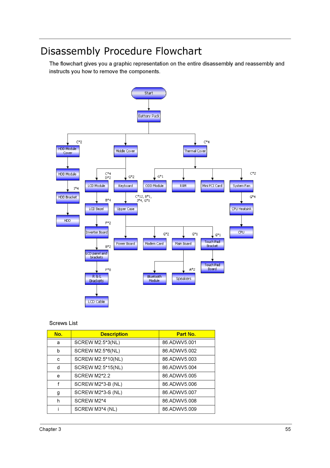
The flowchart gives you a graphic representation on the entire disassembly and reassembly and instructs you how to remove the components.
Screws List
No. | Description | Part No. |
|
|
|
a | SCREW M2.5*3(NL) | 86.ADWV5.001 |
|
|
|
b | SCREW M2.5*6(NL) | 86.ADWV5.002 |
|
|
|
c | SCREW M2.5*10(NL) | 86.ADWV5.003 |
|
|
|
d | SCREW M2.5*15(NL) | 86.ADWV5.004 |
|
|
|
e | SCREW M2*2.2 | 86.ADWV5.005 |
|
|
|
f | SCREW | 86.ADWV5.006 |
|
|
|
g | SCREW | 86.ADWV5.007 |
|
|
|
h | SCREW M2*4 | 86.ADWV5.008 |
|
|
|
i | SCREW M3*4 (NL) | 86.ADWV5.009 |
|
|
|
Chapter 3 | 55 |
