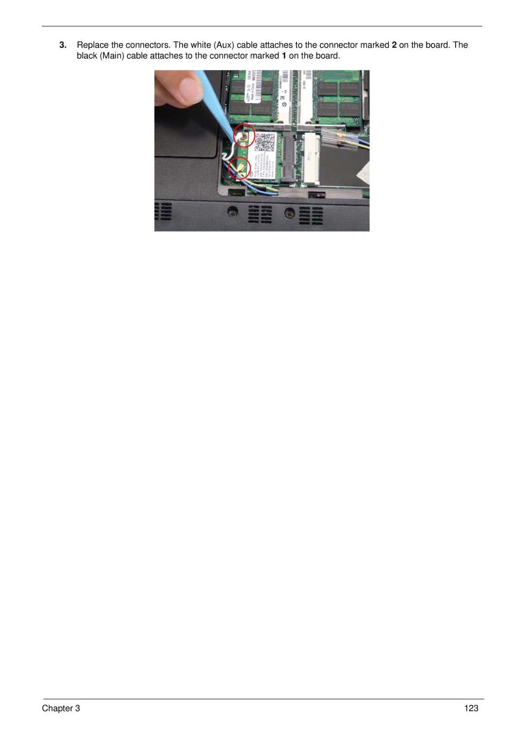
3.Replace the connectors. The white (Aux) cable attaches to the connector marked 2 on the board. The black (Main) cable attaches to the connector marked 1 on the board.
Chapter 3 | 123 |
3.Replace the connectors. The white (Aux) cable attaches to the connector marked 2 on the board. The black (Main) cable attaches to the connector marked 1 on the board.
Chapter 3 | 123 |