Manuals
/
Brands
/
Computer Equipment
/
Laptop
/
Acer
/
Computer Equipment
/
Laptop
Acer
1410, 1810T, 752
- page 92
1
92
256
256
Download
256 pages, 5.25 Mb
82
Chapter 3
Removing the Camera Board
1.
See “Removing the LCD Bezel” on page 79.
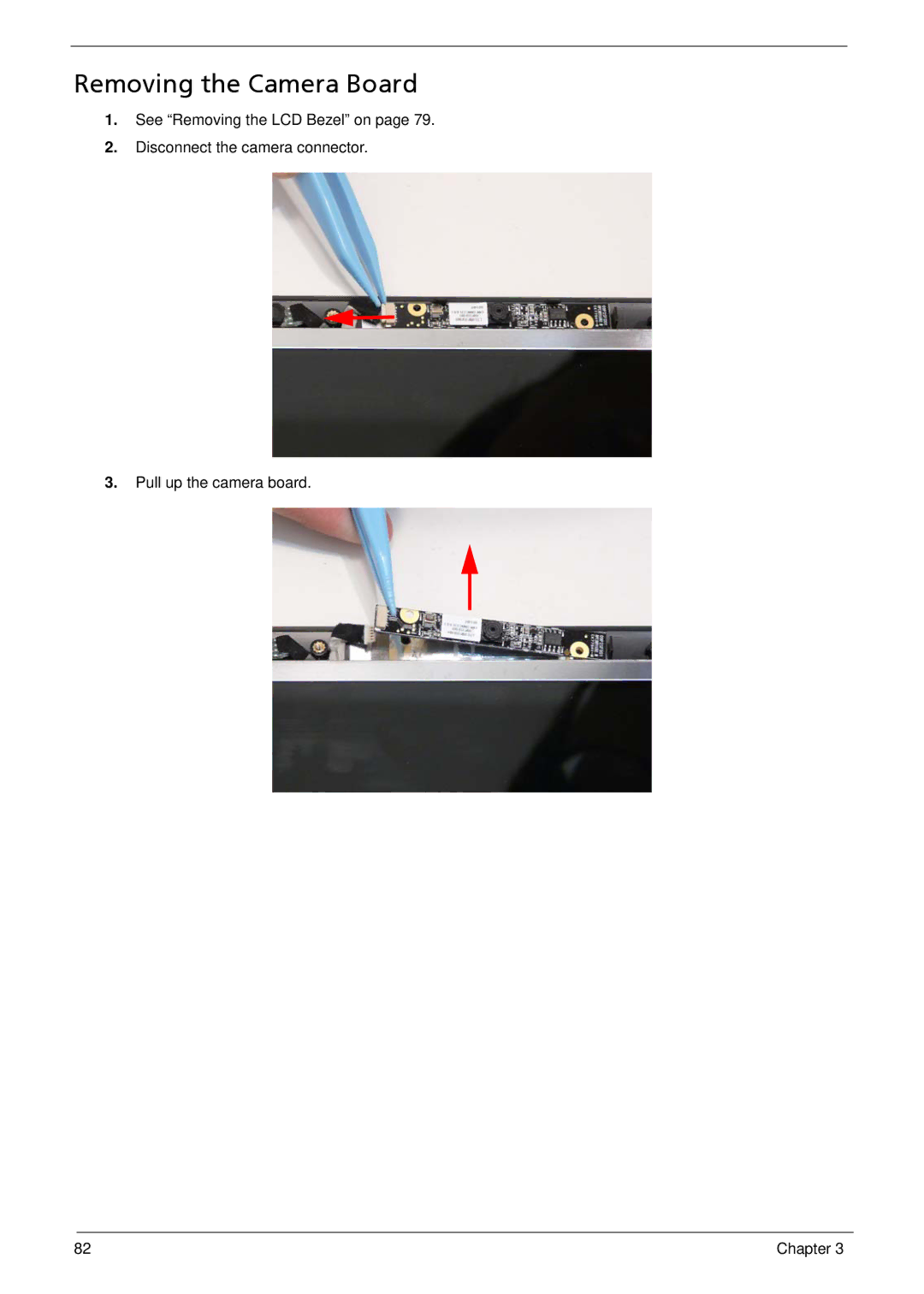
2.
Disconnect the camera connector.
3.
Pull up the camera board.
Contents
Main
Page
Copyright
Disclaimer
Conventions
Preface
Page
System Specifications 1
System Utilities 25
Machine Disassembly and Replacement 41
Troubleshooting 131
Page
Page
System Specifications
Chapter 1
Features
Operating System
Platform
Page
Environment
4Chapter 1
System Block Diagram
CantigaSFFGS45
NORTH BRIDG E
PenrynSFFUL V DC/SC
SOUTHBRIDGE ICH9-MSFF
Your Notebook Tour
Front View
Closed Front View
Left View
Right View
g
Base View
Rear View
Indicators
TouchPad Basics
Using the Keyboard
Lock Keys and embedded numeric keypad
Windows Keys
Hot Keys
Special Keys
Hardware Specifications and Configurations
Page
Page
Page
Page
Page
Page
Page
Page
Page
System Utilities
Chapter 2
BIOS Setup Utility
Navigating the BIOS Utility
Information
Main
Security
Setting a Password
Page
Page
Boot
Exit
Page
DOS Flash Utility
Page
Remove HDD/BIOS Password Utilities
Page
Miscellaneous Utilities
Using Boot Sequence Selector
Using DMITools
Example 1: Read DMI Information from Memory
Example 2: Write Product Name to EEPROM
Using the LAN MAC Utility
Page
Machine Disassembly and Replacement
Chapter 3
Disassembly Requirements
Related Information
Replacement Requirements
Page
Disassembly Process
External Module Disassembly Process
External Modules Disassembly Flowchart
Page
Page
Page
Page
Page
Page
Page
Page
Page
54 Chapter 3
Main Unit Disassembly Process
Main Unit Disassembly Flowchart
Page
Removing the Keyboard
Page
Removing the Upper Cover
Page
Page
Page
Page
Page
Page
Page
Page
Page
Page
Page
Page
Removing the Mainboard
Page
Page
Page
Page
Page
Page
LCD Module Disassembly Process
LCD Module Disassembly Flowchart
Page
Page
Page
Page
Page
Page
Page
Page
Page
Page
Page
LCD Reassembly Procedure
Replacing the Antennas
Page
Page
Page
Page
Page
Page
Page
Page
Page
Page
Page
Page
Page
Replacing the Thermal Module
Page
Page
Page
Page
Page
Page
Page
Page
Page
Page
Page
Page
Page
Page
Page
Page
Page
Page
Page
Page
Page
Page
Page
Page
Page
Page
Troubleshooting
Chapter 4
Common Problems
Power On Issue
Computer Shuts down Intermittently
No Display Issue
No POST or Video
Abnormal Video Display
Random Loss of BIOS Settings
Chapter 4 135
6. If the Issue is still not resolved, see Online Support Information on page 241.
LCD Failure
Built-In Keyboard Failure
Chapter 4 137
TouchPad Failure
Internal Speaker Failure
Sound Problems
Internal Microphone Failure
Microphone Problems
HDD Not Operating Correctly
USB Failure (Right up/down side)
Other Failures
Intermittent Problems
Undetermined Problems
POST Code Reference Tables
Page
Page
Page
Jumper and Connector Locations
Chapter 5
Mainboard Top View
Mainboard Bottom View
BOTTOM SIDE
Clearing Password Check and BIOS Recovery
Mainboard CMOS Discharge
BIOS Recovery by Crisis Disk
BIOS Recovery Boot Block
BIOS Recovery Hotkey
Steps for BIOS Recovery from USB Storage
FRU (Field Replaceable Unit) List
152 Chapter 6
Main Assembly
Item Description Part Number
LCD Assembly
Camera
FRU List
Page
Page
Page
Page
Page
Page
Model Definition and Configuration
Appendix A
Aspire 1810T/1410
Page
Page
Page
Page
Page
Page
Page
Page
Page
Page
Page
Page
Page
Page
Page
Page
Page
Page
Page
Page
Page
Page
Page
Page
Page
Page
Page
Page
Page
Page
Page
Page
Page
Page
Page
Page
Page
Page
Page
Page
Page
Page
Page
Page
Page
Page
Page
Page
Page
Page
Page
Page
Page
Page
Page
Page
Page
Aspire One 752
Page
Page
Page
Page
Page
Page
Page
Page
Page
Page
Page
Test Compatible Components
Appendix B
Aspire 1810T/1410
Page
Page
Page
Aspire One 752
Page
Page
Page
Page
Online Support Information
Appendix C
Page
Index
A
B
C
D
M
N
O
P
S