Acer | Acer |
Assembly and Disassembly (continue)
|
|
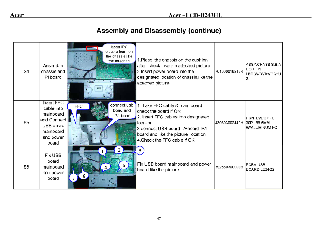
| Insert IPC |
|
|
|
|
|
|
|
|
| |
|
|
| electric foam on |
|
|
|
|
|
|
|
|
| |
|
|
| the chassis like | 1.Place the chassis on the cushion |
|
|
|
|
| the attached |
| ASSY,CHASSIS,B,A | |
| Assemble | after check, like the attached picture. |
| |||
S4 | chassis and | 2.Insert power board into the | 701000018213R | UO THIN | ||
| PI board | designated location of chassis,like the |
| LED,W/DVI+VGA+U | ||
|
| S | ||||
|
|
|
| attached picture. |
|
|
| Insert FFC |
| FFC |
| connect usb | 1. Take FFC cable & main board, |
|
|
| cable into |
|
|
|
| |||
|
|
|
| boad and | check the board if OK; |
|
| |
| mainboard |
|
|
|
|
| ||
|
|
|
| P/I bord | 2. Insert FFC cables into designated |
| HRN LVDS FFC | |
S5 | and Connect |
|
|
|
| |||
|
|
|
| location ; | 430303002440H | |||
USB board |
|
|
|
| 30P 166.5MM | |||
|
|
|
|
| 3.connect USB board ,I/Fboard P/I |
| W/ALUMINUM FO | |
| mainboard |
|
|
|
|
| ||
|
|
|
|
| board and like the picture location |
|
| |
| and power |
|
|
|
|
|
| |
|
|
|
|
| 4.Check the FFC cable if OK |
|
| |
| board |
|
|
|
|
|
| |
|
|
|
|
|
|
|
| |
| Fix USB |
| 1 |
| 2 | 3 |
|
|
|
|
|
|
|
|
|
| |
| board |
|
|
| 5 | Fix USB board mainboard and power |
| PCBA,USB |
S6 | mainboard |
|
| 4 | 792680300000H | |||
| and power |
|
|
|
| board like the picture. |
| BOARD,LE24Q2 |
|
| 6 |
|
|
|
|
| |
| board | 7 |
|
|
|
|
| |
|
|
|
|
|
|
|
47