4. Assembly and Disassembly Procedures (continued)
ACER X193HQ |
| 13 |
|
|
|
Go to cover page
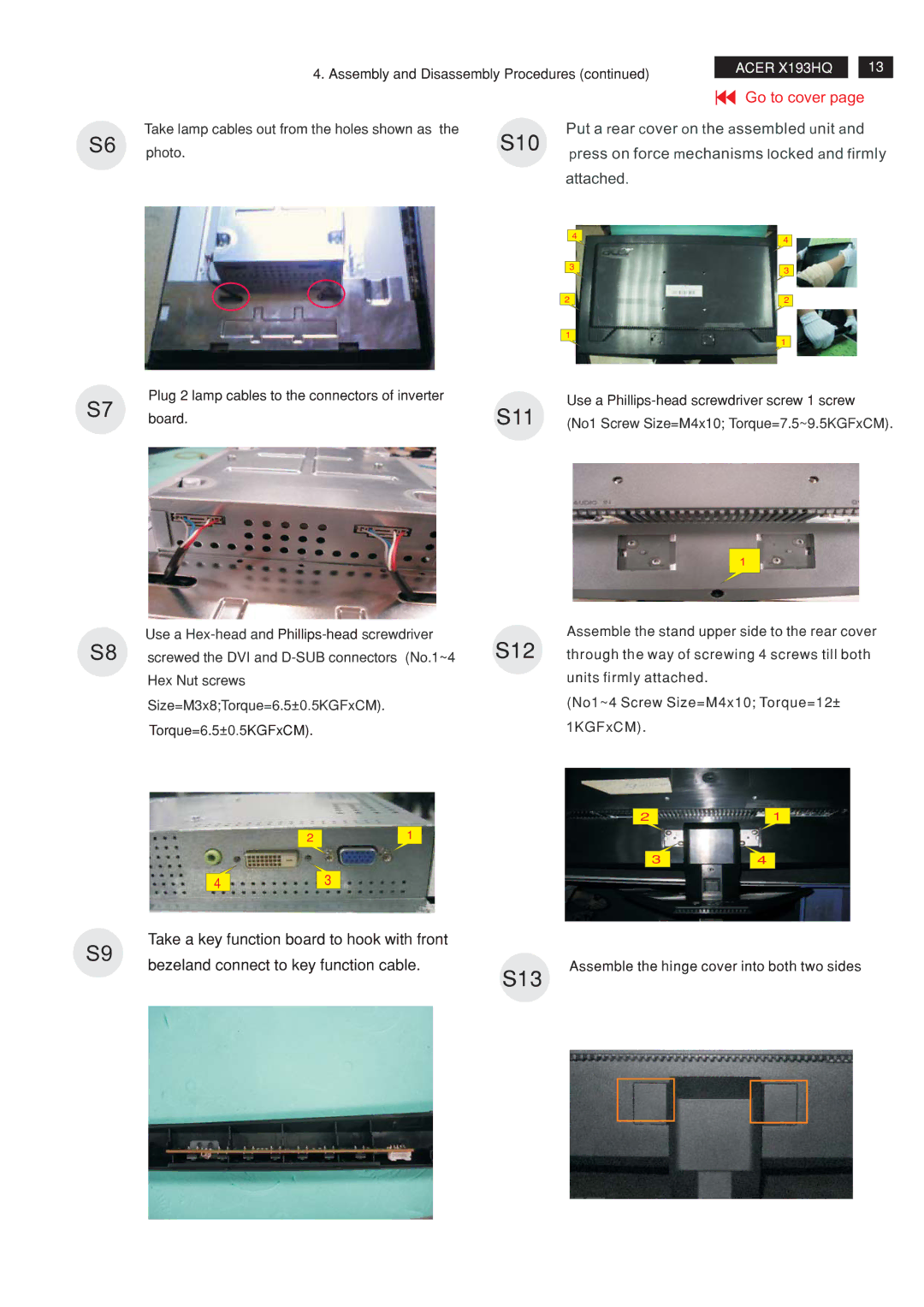
S6 | Take lamp cables out from the holes shown as the | S10 | Put a rear cover on the assembled unit and | ||
photo. | press on force mechanisms locked and firmly | ||||
|
| ||||
|
|
| attached. |
| |
|
|
| 4 | 4 | |
|
|
|
| ||
|
|
| 3 | 3 | |
|
|
|
| ||
|
|
| 2 | 2 | |
|
|
| 1 | 1 | |
|
|
|
| ||
S7 | Plug 2 lamp cables to the connectors of inverter |
| Use a | ||
| S11 | ||||
board. | (No1 Screw Size=M4x10; Torque=7.5~9.5KGFxCM). | ||||
| |||||
|
|
| 1 |
| Use a | S12 | Assemble the stand upper side to the rear cover |
S8 | screwed the DVI and | through the way of screwing 4 screws till both | |
| Hex Nut screws |
| units firmly attached. |
| Size=M3x8;Torque=6.5±0.5KGFxCM). |
| (No1~4 Screw Size=M4x10; Torque=12± |
| Torque=6.5±0.5KGFxCM). |
| 1KGFxCM). |
|
| 2 | 1 |
| 2 | 1 |
|
|
|
| |
|
| 3 | 4 |
4 |
| 3 |
|
|
|
|
Take a key function board to hook with front
S9 | bezeland connect to key function cable. | Assemble the hinge cover into both two sides | ||||
| ||||||
|
| S13 | ||||
|
|
|
|
|
|
|
|
|
|
|
|
|
|