AdderView CATx
Contents
Auto calibrate
Re-synchronise mouse
Index
Introduction
AdderView CATx features front and rear
Front panel buttons
What’s in the box
What you may additionally need
Connections
Mounting
Rack brackets
Remote switching Control
Connections
Modem Multiple video Isdn port Head connections
Cascading Multiple units
Local user
To connect the local user port
To connect a remote user
Remote user via X100/X200 extender
Cable lengths for remote user locations
Global user IP network port
To connect the Global user IP network port
Computer video compensation for details
Computer system via CAM
To connect a computer system
Modem/ISDN port
To connect a modem or Isdn adapter
Power in connection
To connect the power supply
Power control port
To connect and address the switch boxes
See also
Cascading multiple units
System, called Adder Port Direct
How cascade connections operate
Addressing computers in a cascade
CA02
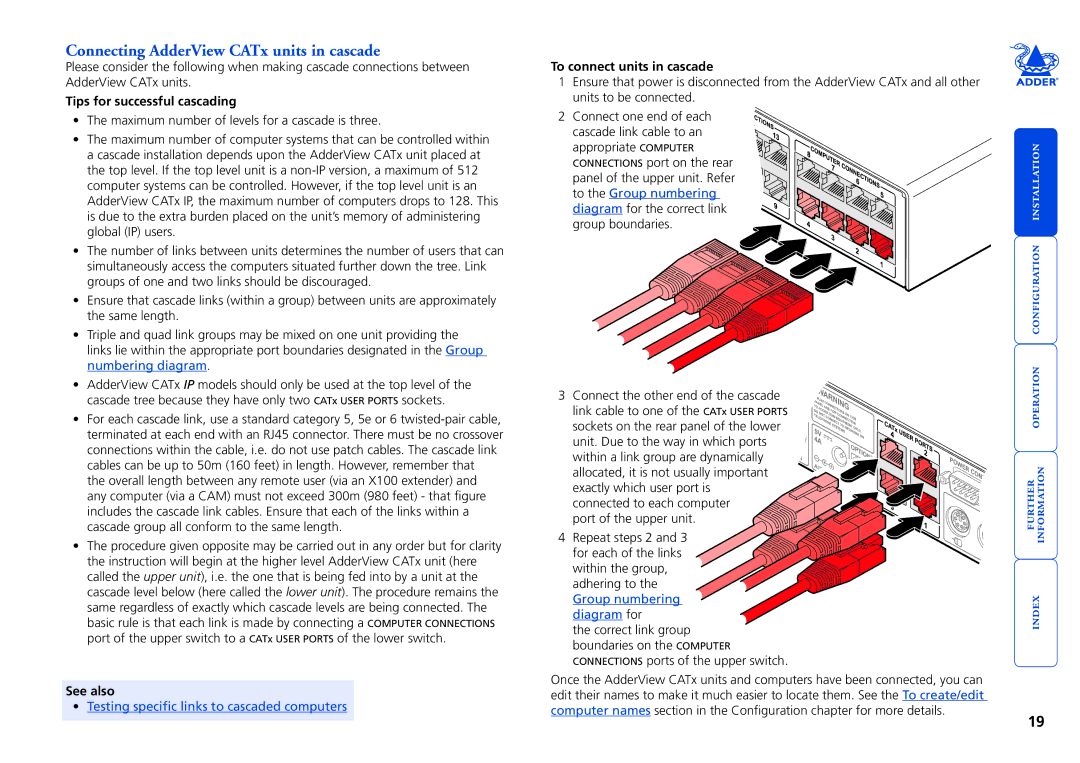
To connect units in cascade
Connecting AdderView CATx units in cascade
Tips for successful cascading
To test a specific link
Using cascaded computers
Testing specific links to cascaded computers
Multiple video head connections
Remote switching control
Host computer port/channel Video off
Overall initial configuration
Configuration menus
To access the configuration menu local and remote users
To access the configuration menu global users
Hotkeys
General security and configuration steps
Configuration menus layout
To enable general security
To set an Admin password
To create/edit user accounts
Access to all computers Press Access to no computers Press
Registering users edit user list
To create/edit computer entries
Tips when creating/editing computer entries
Registering computers edit computer list
See Remote user skew adjustment for details
Video compensation
Computer video compensation
To apply computer video compensation
Remote user video compensation
To display a suitable high contrast image
To apply remote user video compensation
If the image controls cannot provide a crisp image
Remote user skew adjustment
To use skew adjustment
Using the supplied skew pattern
Creating a skew test pattern
Num Lock for Red, Caps Lock for Green
To select an autoscan mode
Autoscanning
To select an autoscan period
To define an autoscan list
To transfer configuration settings
Saving and restoring configuration settings
Preparations for configuration save/load
To edit the configuration settings
Hints for editing
What to do if the Admin password has been forgotten
To reset AdderView CATx models
To reset the AdderView CATx IP models
Configuration screens
Which restore setting do I use?
To restore mouse operation when hot plugging
Hot plugging and mouse restoration
Recognising an IntelliMouse-style mouse
To configure IP-specific settings
Initial IP configuration
To use the initial IP-configuration sequence
User Accounts
IP configuration by global user
To configure IP details from a global user location
Viewer encryption settings
Encryption settings
AdderView CATx IP encryption settings
Networking issues
Positioning AdderView CATx IP in the network
Addressing
Port settings
Placing AdderView CATx IP behind a router or firewall
To discover a DHCP-allocated IP address
DNS addressing
By configuration page via viewer
Placing AdderView CATx IP alongside the firewall
Ensuring sufficient security
Ports
Power switching configuration
Power control sequences
To configure the power sequences for each host computer
To control two or more ports simultaneously
Kvmadmin utility
Kvmadmin command ip address parameters
Kvmadmin -getconfig kvm1.cfg
Kvmadmin -setusers users.csv
Performing upgrades
Items required to use the upgrade utility
Upgrading AdderView CATx models and CAMs
To use the KVM Firmware Uploader utility
Select the items to be upgraded
Select the upgrade file to be used
Commence the upgrade
Issues to consider when performing flash upgrades
To upgrade AdderView CATx IP models
Upgrading AdderView CATx IP models
Accessing the AdderView CATx
Front panel controls
AdderView CATx models
AdderView CATx IP models
Local and remote user access
To gain access as a local or remote user
To select a computer using the front panel controls
Selecting a computer
To select a computer using hotkeys
Standard hotkeys
Above or for even longer cascaded computers
Keep Pressed down until all other Numbers have been entered
To select a computer using mouse buttons Advanced method
To select a computer using the on-screen menu
To select a computer using mouse buttons
Confirmation box
Logging in and out
Selecting cascaded computers
To change banner colours or disable the banner
To use the Routing status feature
Reminder banner
Routing status
User preferences and functions
Power switching via configuration menu
To switch a computer on or off
Global user access
To download the VNC viewer
Global user access via VNC viewer
To access via the VNC viewer
Global user access via web browser
To access via your web browser
Menu bar
Using the viewer window
When using the viewer window
Configure
Mouse pointers
Host selection
To select a host
Access mode shared/private
Power switching via viewer
Auto calibrate
Re-synchronise mouse
Single Mouse Mode
Controls
Mouse Control
Resync Mouse
When entering codes
Video Settings
KVM switch menu
Keyboard Control
Using automatic configurations
Increased by 50% when a slow link is detected
Setting the Threshold manually
System information
Access via dial up modem or Isdn link
If you need to enter a port number
To initiate a dial up link
To enter a port number in a Web browser
Viewer encryption settings
Supported web browsers
Windows
Linux
Troubleshooting
When logging on using VNC viewer, I cannot enter a username
Getting assistance
US +1 888 275
Configure IP port
Appendix 1 Configuration menus
To access the configuration menus
Functions
User Preferences
Mouse Switching
Autoscan Mode
Global Preferences
Screen Saver
User Timeout
OSD Dwell Time
RS232 Mouse Type
Mouse Type
Setup Options
Keypad Controls
Language
Exclusive Use
Settings AUTO, Manual
Automatic Logout
Audio
Add Computers
DDC Source Settings AUTO, LOCAL, Default
DDC Refresh Settings AT START, Disabled
Advanced Options
DDC Options
Country Code Settings AUTO, MANUAL, Disabled
Default Country
Setup Options
Force Mode Settings DISABLED, Enabled
Configure IP port
IP admin password, encryption settings, etc
IP address, net mask, VNC port, etc
Baud rate, initialisation string, etc
Unit Configuration
Network Configuration
Modem Configuration
Clearing IP access control
Reset Configuration
To reset the AdderView CATx IP configuration
What is IP access control?
Appendix 2 Configuration pages via viewer
To access the remote configuration pages
User accounts
Unit configuration
Admin Password
Hardware Version
Firmware Version
Advanced unit configuration
Time & date configuration
Network configuration
IP Access Control
IP Network Mask
IP Gateway
Setting IP access control
To define a new IP access control entry
To reorder access control entries
To edit/remove access control entries
Modem port
Serial port configuration
Power control port
Host configuration
Erase Host Configuration
Add entry for unrecognised host
To create a new host entry
Examples
Port/host addressing using Adder Port Direct
Adder Port Direct
Logging and status
To copy and paste the log
Syslog Server IP Address
For further details To get here
Appendix 3 VNC viewer connection options
Colour/Encoding
Auto select
Preferred encoding
Enable all inputs
Disable all inputs view-only mode
Inputs
Customise
Scaling
Misc
Defaults Reload
Defaults Save
Identities
Load / Save
Appendix 4 VNC viewer window options
Security
Appendix 5 Browser viewer options
Encoding and colour level
Appendix 6 Addresses, masks and ports
IP addresses
Net masks
Want to know more?
154
Net masks the binary explanation
Calculating the mask for IP access control
Single locations
All locations
Address ranges
Security issues with ports
Ports
RS232 serial flash upgrade cable
Appendix 7 Cable and connector specifications
Power switch to power switch daisy chain cable
Multi-head synchronisation cable
Creating macro sequences
Appendix 8 Hotkey sequence codes
Permissible key presses
Appendix 9 Supported video modes
General Public License Linux
Warranty
Safety information
End user licence agreement
Radio Frequency Energy
European EMC directive 89/336/EEC
FCC Compliance Statement United States
Canadian Department of Communications RFI statement
111
Index
113
114