TRACER 4106/4206 System Manual | Section 2 Microwave Path Engineering Basics |
|
|
6.ANTENNA INFORMATION
The overall wireless system is directly affected by the antenna selection and installation. The following sections discuss several factors concerning antenna selection and installation.
Verify the antenna installation meets all regulations specified in the National Electric Code (NEC) Article 810.
Antenna Alignment
With
TRACER RSSI Test Points
The RSSI indicator for the TRACER 4106/4206 system is provided through the VT100 terminal menus accessed through the
If both the local and remote end of the system are operational, the remote TRACER 4106/4206 receive power can be viewed from the local TRACER 4106/4206 VT100 terminal menu interface.
An RSSI test point, located on the front panel, provides a DC voltage level (relative to the GND test point) that corresponds to the amount of signal being received from the far end's transmitter. The voltage at this test point can vary from approximatly 0 to 5 Volts DC. An RSSI Calibration sheet is shipped with the system to provide the installer a
Antenna Beam Patterns
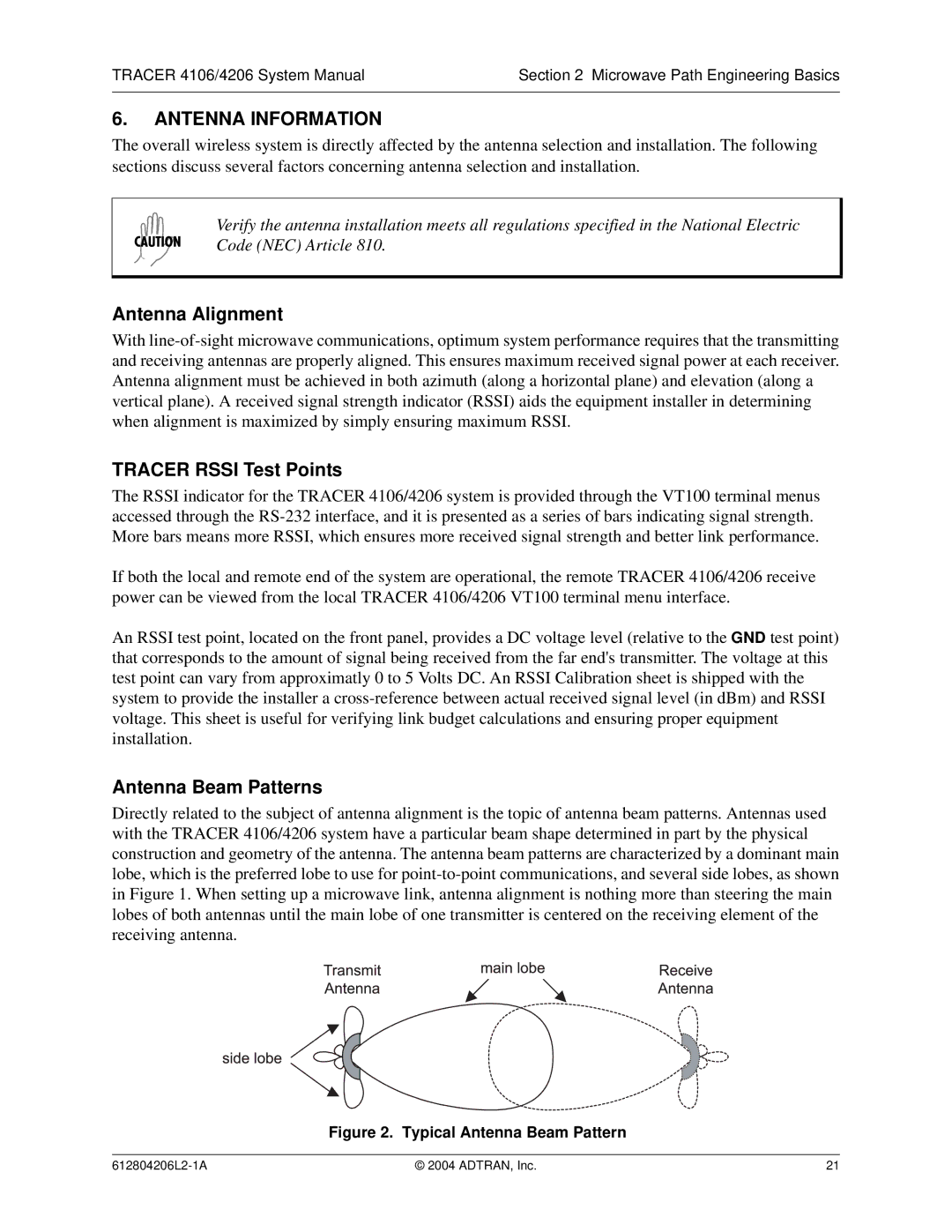
Directly related to the subject of antenna alignment is the topic of antenna beam patterns. Antennas used with the TRACER 4106/4206 system have a particular beam shape determined in part by the physical construction and geometry of the antenna. The antenna beam patterns are characterized by a dominant main lobe, which is the preferred lobe to use for
Figure 2. Typical Antenna Beam Pattern
© 2004 ADTRAN, Inc. | 21 |