Section 3 Engineering Guidelines | TRACER 4106/4206 System Manual |
|
|
screen.
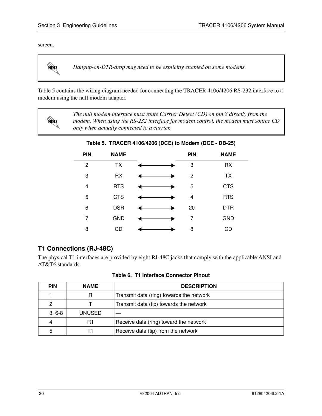
Table 5 contains the wiring diagram needed for connecting the TRACER 4106/4206
The null modem interface must route Carrier Detect (CD) on pin 8 directly from the modem. When using the
Table 5. TRACER 4106/4206 (DCE) to Modem (DCE - DB-25)
PIN | NAME |
|
|
| PIN | NAME |
|
|
|
|
|
|
|
2 | TX |
|
| 3 | RX | |
| ||||||
3 | RX |
|
| 2 | TX | |
| ||||||
4 | RTS |
|
| 5 | CTS | |
| ||||||
5 | CTS |
|
| 4 | RTS | |
| ||||||
6 | DSR |
|
| 20 | DTR | |
| ||||||
7 | GND |
|
| 7 | GND | |
| ||||||
8 | CD |
|
| 8 | CD | |
| ||||||
T1 Connections (RJ-48C)
The physical T1 interfaces are provided by eight
|
| Table 6. T1 Interface Connector Pinout | |
|
|
|
|
PIN | NAME |
| DESCRIPTION |
|
|
|
|
1 | R |
| Transmit data (ring) towards the network |
|
|
|
|
2 | T |
| Transmit data (tip) towards the network |
|
|
|
|
3, | UNUSED |
| — |
|
|
|
|
4 | R1 |
| Receive data (ring) toward the network |
|
|
|
|
5 | T1 |
| Receive data (tip) from the network |
|
|
|
|
30 | © 2004 ADTRAN, Inc. |