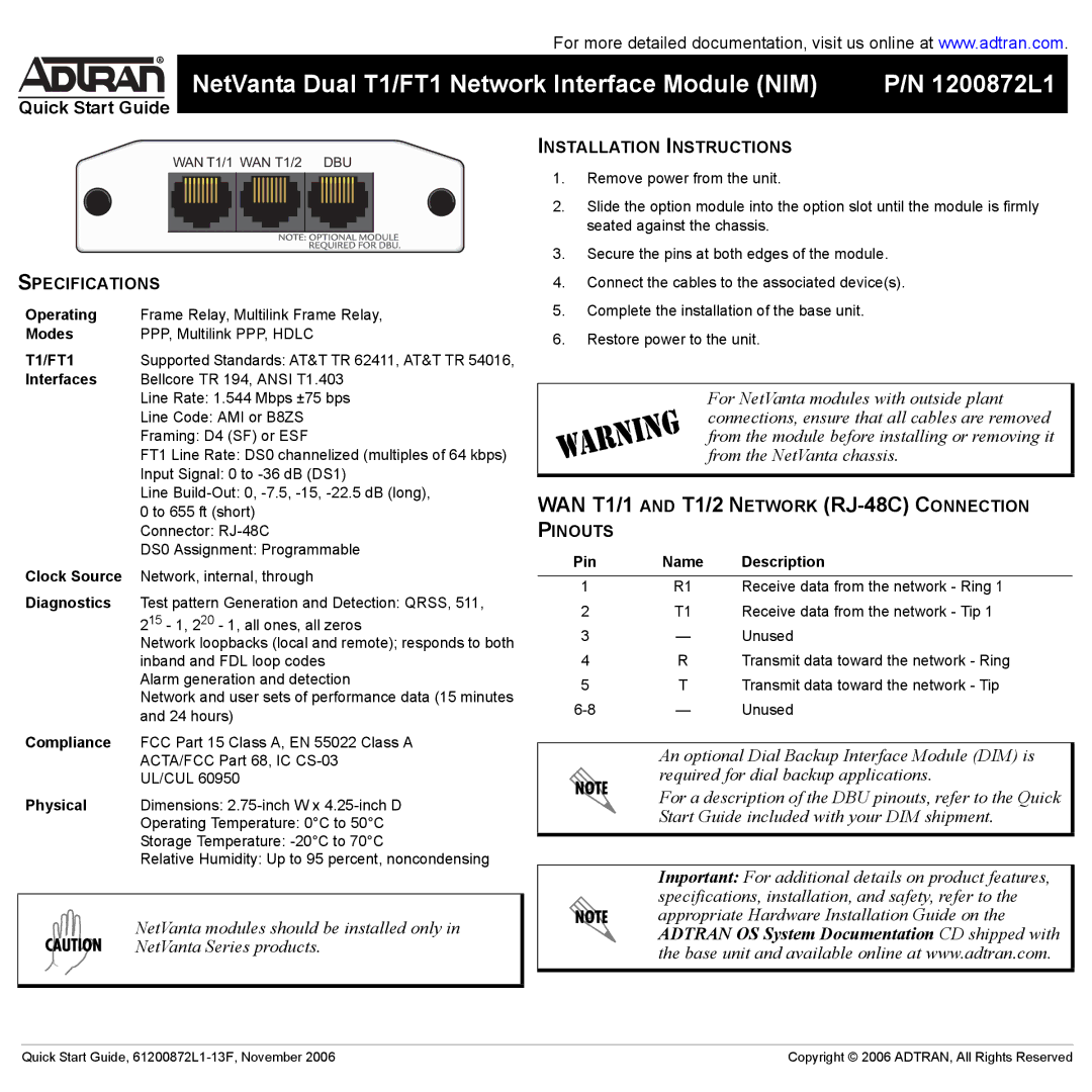
T1 specifications
ADTRAN T1 technology plays a vital role in telecommunications by providing reliable and high-quality voice and data transmission. Widely adopted by businesses and service providers, ADTRAN’s T1 equipment offers numerous advantages, including robust performance, ease of use, and scalability.One of the key features of ADTRAN T1 is its ability to accommodate multiple voice and data channels simultaneously. A standard T1 line can handle up to 24 voice channels, each operating at 64 Kbps, which allows for an effective bandwidth of 1.544 Mbps. This capability makes it an ideal choice for organizations that require efficient communication solutions. ADTRAN’s T1 equipment also supports various modulation and encoding schemes that enhance the quality of service and reduce latency.
ADTRAN incorporates advanced technologies such as Echo Cancellation, which minimizes signal interference and maximizes clarity during calls. This is particularly beneficial in environments where multiple calls are taking place, as it helps maintain consistent audio quality. Additionally, ADTRAN T1 implementations often support Integrated Access Devices (IADs), which combine voice and data functions into a single device, streamlining network management and reducing costs.
Another important characteristic of the ADTRAN T1 system is its reliability. T1 lines are known for their stability and uptime, making them a preferred option for mission-critical applications. ADTRAN’s T1 products come equipped with network monitoring tools that allow administrators to track performance metrics and promptly identify issues, ensuring smooth operability.
Scalability is another prominent feature of ADTRAN T1. Businesses can easily upgrade their existing infrastructure to accommodate future growth without significant overhauls. The modular design of ADTRAN’s equipment allows for the addition of more channels or integration with newer technologies, such as VoIP and high-speed internet, ensuring businesses stay competitive.
In conclusion, ADTRAN T1 technology stands out due to its combination of high capacity, reliability, and advanced features. It serves as a robust platform for organizations seeking efficient voice and data solutions. With its emphasis on performance, scalability, and integrated management, ADTRAN continues to be a leader in T1 telecommunications, empowering businesses to optimize their communication infrastructures and meet today’s demands.