sealing washer |
flat washer |
bolt |
split washer |
Bolt torque: |
Insert all unused fasteners |
*1/2"
*3/8" x
*1/2" Nut
*1/2" Washer
Pole Mount
Bracket
![]() Pole Support Brackets (2)
Pole Support Brackets (2)
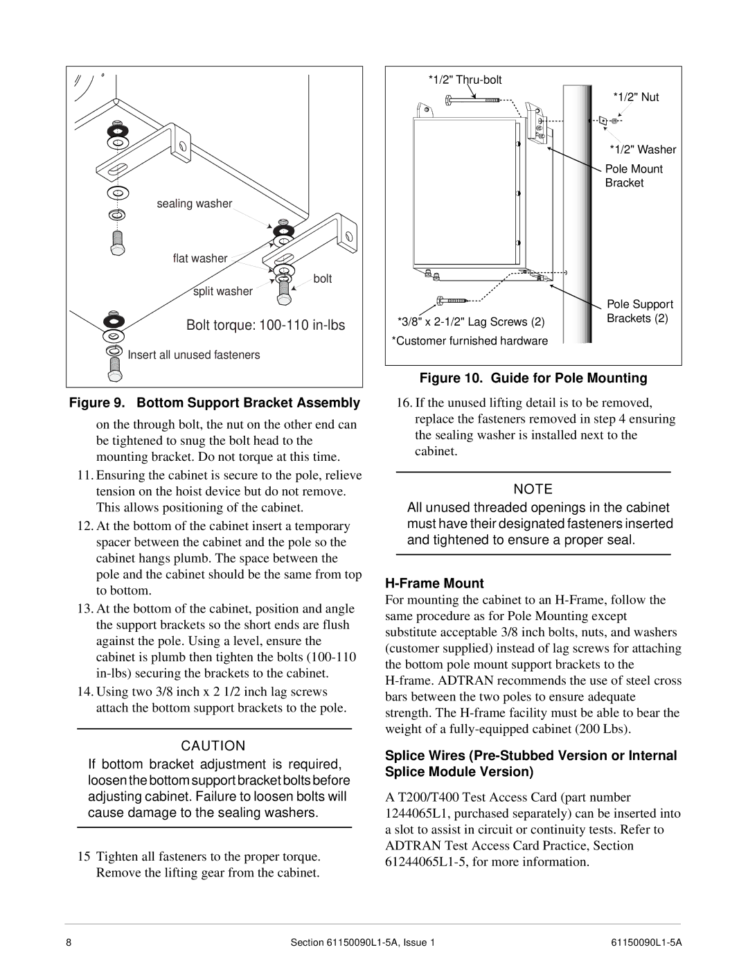
Figure 9. Bottom Support Bracket Assembly
on the through bolt, the nut on the other end can be tightened to snug the bolt head to the mounting bracket. Do not torque at this time.
11.Ensuring the cabinet is secure to the pole, relieve tension on the hoist device but do not remove. This allows positioning of the cabinet.
12.At the bottom of the cabinet insert a temporary spacer between the cabinet and the pole so the cabinet hangs plumb. The space between the pole and the cabinet should be the same from top to bottom.
13.At the bottom of the cabinet, position and angle the support brackets so the short ends are flush against the pole. Using a level, ensure the cabinet is plumb then tighten the bolts
14.Using two 3/8 inch x 2 1/2 inch lag screws attach the bottom support brackets to the pole.
CAUTION
If bottom bracket adjustment is required, loosen the bottom support bracket bolts before adjusting cabinet. Failure to loosen bolts will cause damage to the sealing washers.
15Tighten all fasteners to the proper torque. Remove the lifting gear from the cabinet.
Figure 10. Guide for Pole Mounting
16.If the unused lifting detail is to be removed, replace the fasteners removed in step 4 ensuring the sealing washer is installed next to the cabinet.
NOTE
All unused threaded openings in the cabinet must have their designated fasteners inserted and tightened to ensure a proper seal.
H-Frame Mount
For mounting the cabinet to an
Splice Wires
A T200/T400 Test Access Card (part number 1244065L1, purchased separately) can be inserted into a slot to assist in circuit or continuity tests. Refer to ADTRAN Test Access Card Practice, Section
8 | Section |
|
