6.Disconnect the door switch JP2 connector on the fan board by carefully pulling the connector off the header. DO NOT PULL ON WIRES.
7.Take an insulated
8.If the Door LED goes Off, the door switch is defective.
9.Follow the door switch replacement Instructions to replace the defective door switch.
NOTE
Refer to the Fan Powering Unit I&M Practice:
4. MAINTENANCE
Maintenance consists of replacement of surge arrester gas tubes, door gaskets, or other replaceable items. Fan board repairs should not be attempted in the field. Repair services are obtained by returning the defective unit to ADTRAN Customer Service.
Refer to Table 7 for a list of replacement item part numbers.
Table 7. Replacement Item Part Numbers
Description | Part Number |
|
|
Desiccant, 8 Oz. Bag | 3168001 |
|
|
Gas Tubes | 3186001 |
|
|
Gas Tube Insert/Extract Tool | 3269042 |
|
|
Primary Fan Board | |
|
|
Secondary Fan Board | |
|
|
Pad Mount Kit | |
|
|
Pole Mount Kit | |
|
|
Cable Stub Mount Kit | |
|
|
Door Gasket Repair Kit | |
|
|
Door Switch Repair Kit | |
|
|
Desiccant Renewal
Each cabinet is shipped with two moisture absorbing desiccant bags inside the cabinet. To ensure continued moisture absorption the desiccant must be renewed periodically, depending on the environment.
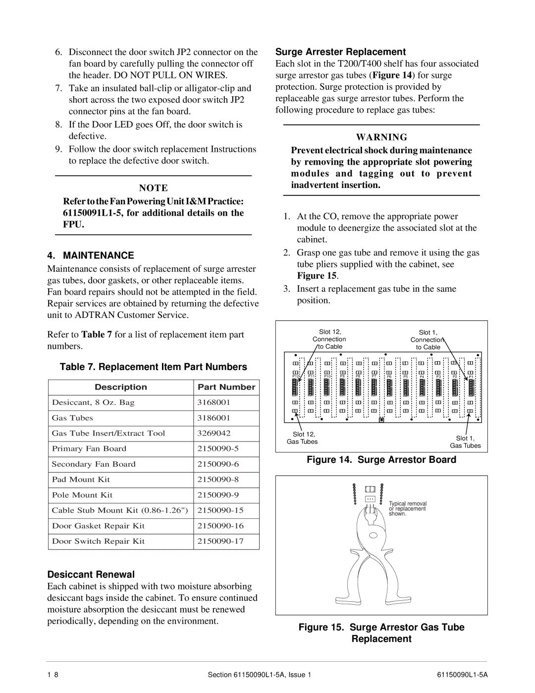
Surge Arrester Replacement
Each slot in the T200/T400 shelf has four associated surge arrestor gas tubes (Figure 14) for surge protection. Surge protection is provided by replaceable gas surge arrestor tubes. Perform the following procedure to replace gas tubes:
WARNING
Prevent electrical shock during maintenance by removing the appropriate slot powering modules and tagging out to prevent inadvertent insertion.
1.At the CO, remove the appropriate power module to deenergize the associated slot at the cabinet.
2.Grasp one gas tube and remove it using the gas tube pliers supplied with the cabinet, see Figure 15.
3.Insert a replacement gas tube in the same position.
|
| Slot 12, |
|
|
|
| Slot 1, |
|
| ||
| Connection |
|
|
|
| Connection |
|
| |||
|
| to Cable |
|
|
|
| to Cable |
|
| ||
P12 | P11 | P10 | P9 | P8 | P7 | P6 | P5 | P4 | P3 | P2 | P1 |
Slot 12,
Gas TubesSlot 1,
Gas Tubes
Figure 14. Surge Arrestor Board
Typical removal or replacement shown.
Figure 15. Surge Arrestor Gas Tube
Replacement
1 8 | Section |
|