PCM-9588
Acknowledgements
Copyright
Warranty Period
Product Warranty 2 years
Repairs under Warranty
Exclusions from Warranty
FCC Class a
Declaration of Conformity
Technical Support and Assistance
Packing List
Optional accessories
Ordering information
Model Number Description
Page
Contents
Appendix a
Introduction & Installation
Optional Extras for the PCM-9588
Page
Chapter
Introduction
Product Specifications
Chipset
Functional Spec
General Introduction
Other chipset
Chipset ICH6M I/O
Electrical Specifications
Mechanical Specifications
Weight g with Cooler 480 g
Power supply Voltage
PCM-9588 ATX Power Consumption
Operating Humidity
Environment Specifications
Page
W Installation
Jumper list
Jumper Settings
Jumpers
JP9 Backlight control select
JP8 LCD Panel Power Select
Jumper description
Connector list
Connectors
Connector Settings
Connector List
Inverter connector CN6
Power connector CN5
VGA connector CN8
Lvds connector CN9
2.12 PC-104 plus connector CN17
IDE Connector CN16
COM port connector CN19, CN41
USB connectors CN20, CN28, CN38
DVI interface connector CN30
2.20 -V5 and -V12 connector CN27
Sata Connector CN31 and CN32
LAN LED connector CN34
Mechanical
Jumper and Connector Locations
Board Dimension Layout Component Side
Board Dimensions
Page
Bios Operation
Bios Setup
Bios Introduction
Main Menu
Standard Cmos Features
Advanced Bios Features
Boot Up Floppy Seek Disabled
First / Second / Third / Other Boot Drive
Boot Up NumLock Status Disabled
Boot Up NumLock StatusEnabled
Advanced Chipset Features
Integrated Peripherals
Onboard Device
OnChip IDE Device
Super IO Device
Onboard Serial port 1 3F8
Power Management Setup
Power Management Min Saving
Run VGA Bios if S3 Resume Auto
HDD Power Down Disabled
Suspend Mode 1 Hour
Reset Configuration Data Disabled
7 PnP/PCI Configurations
PCI VGA Palette Snoop Disabled
Init Display First PCI Slot
PC Health Status
Shutdown Temperature Disabled
Current System/CPU Temp Show Only
V / 3.3 V / 5 V / 12 V Show Only
Frequency/voltage Control
Load Optimized Defaults
Spread Spectrum Disabled
To Establish Password
Set Password
To Disable Password
Save & Exit Setup
To Change Password
Quit Without Saving
Page
W Introduction & Installation
S/W Introduction
Driver Installation
Windows XP Professional
Other OS
Susi Functions
Susi Application Library
Susi Introduction
VGA Control API
Susi Installation
Watchdog API
Hardware Monitor API
Windows CE
Express Installation
Manual Installation
Susi Sample Programs
Windows Graphics Mode
Sample Programs
SusiDemo.exe
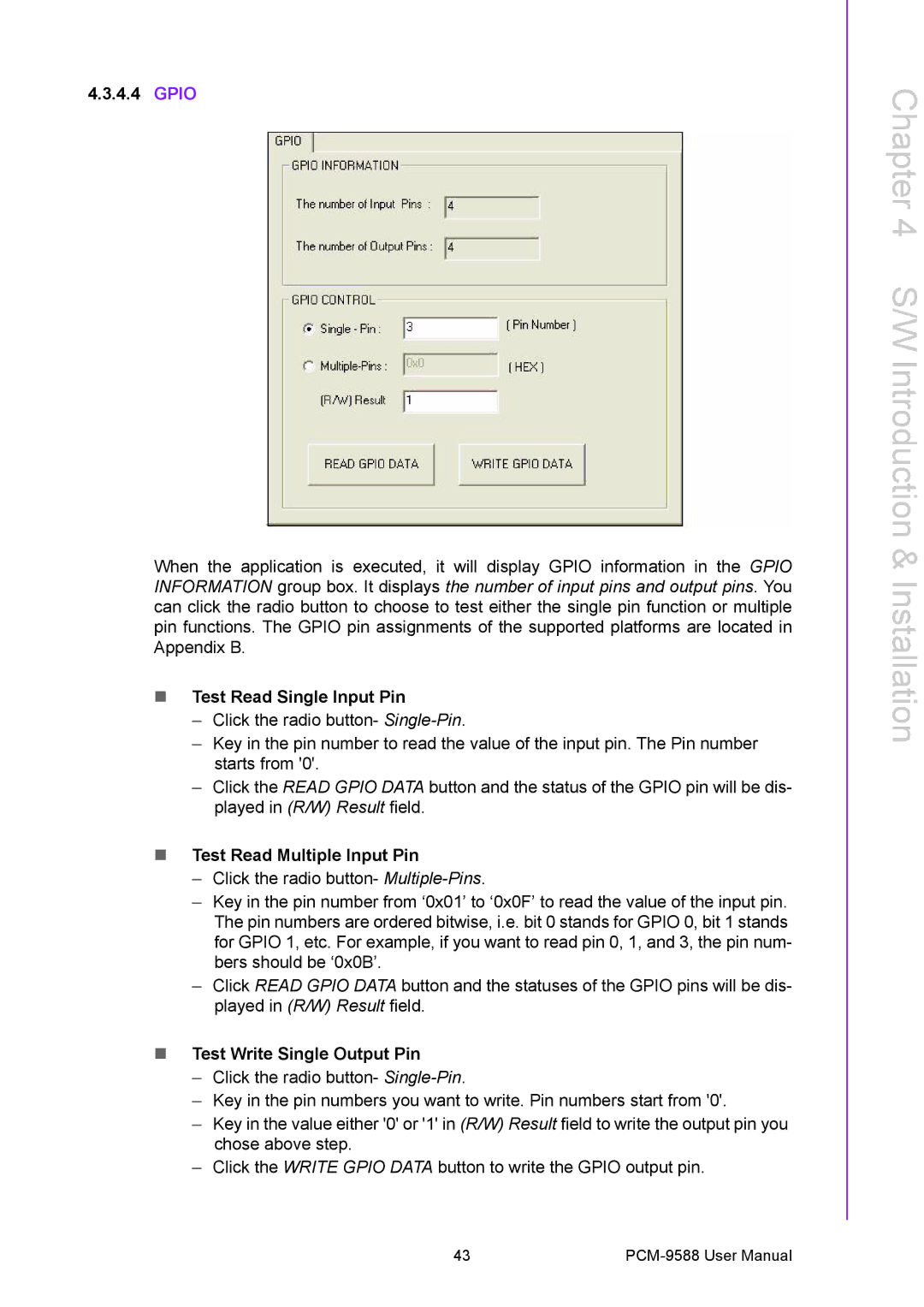
Test Read Single Input Pin
Gpio
Test Read Multiple Input Pin
Test Write Single Output Pin
4.5 I2C
Test Write Multiple Output Pins
Read a byte
Write a byte
Read a word
SMBus
Write Multiple bytes
Write a word
Read Multiple bytes
Brightness control
VGA Control
Screen on/off control
Watchdog
Hardware Monitor
Page
Extension I/O Installation
PCI
PC-104 plus
Appendix a
CN4 Audio connector
CN2 CD in connector
Table A.1 CN2 CD In connector
Table A.2 CN4 Audio connector
Table A.3 CN5 Power connector
CN5 Power connector
CN8 VGA connector
CN6 Inverter connector
Table A.4 CN6 Inverter connector
Table A.5 CN8 VGA connector
Table A.6 CN9 Lvds connector
CN9 Lvds connector
Table A.7 CN10 TTL connector High Bits
CN10 TTL connector High Bits
Table A.8 CN11 TTL connector Low Bits
CN11 TTL connector Low Bits
Table A.9 CN12 LAN connector
CN12 LAN connector
11 CN15 LPT / FDD connector
10 CN13 HDD LED and Power LED
Table A.10 CN13 HDD LED and Power LED
Table A.11 CN15 LPT / FDD connector
Table A.12 CN16 IDE connector
12 CN16 IDE connector
Table A.13 CN17 PC-104/+ Connector
13 CN17 PC104-plus connector
Table A.14 CN19 COM1~4 Connector
14 CN19 COM1~4 connector
16 CN22 Reset Button connector
15 CN20 USB1/2 Connector
Table A.15 CN20 USB1/2 Connector
Table A.16 CN22 Reset Bottom Connector
18 CN24 SIR connector
17 CN23 Power Button connector
Table A.17 CN23 Power Button Connector
Table A.18 CN24 SIR Connector
20 CN26 CF Typeii connector
19 CN25 PS2 Keyboard/Mouse connector
Table A.19 CN25 PS2 Keyboard/Mouse connector
Table A.20 CN26 CF Typeii connector
Table A.21 CN27 -V5 and -V12 connector
21 CN27 -V5 and -V12 connector
Table A.22 CN28 USB3/4 Connector
22 CN28 USB3/4 Connector
23 CN29 DDR2 Sodimm Socket
Table A.23 CN29 DDR2 Sodimm Socket
Table A.24 CN30 DVI Connector
24 CN30 DVI connector
26 CN32 Sata 2 connector
25 CN31 Sata 1 connector
Table A.25 CN31 Sata 1 connector
Table A.26 CN32 Sata 2 connector
28 CN34 LAN LED connector
27 CN33 Battery Connector
Table A.27 CN33 Battery Connector
Table A.28 CN34 LAN LED Connector
30 CN37 GPIO2 Connector
29 CN36 GPIO1 Connector
Table A.29 CN36 GPIO1 Connector
Table A.30 CN37 GPIO2 Connector
32 CN41 COM 5/6 RS-422 / 485 connector
31 CN38 USB5/6 Connector
Table A.31 CN38 USB5/6 Connector
Table A.32 CN41 COM 5/6 / 422 / 485 connector
Appendix B
Table B.1 PCM-10586-9588E Cable kit for PCM-9588
PCM-10586-9588E Cable kit for PCM-9588
Appendix C
Watchdog Timer
RA02 Start
Gpio Sample Code
RA02 Start
Ax=5E78
RA02 Start
Mov Bx,0400h Int 15h RA02 END Check GPI 1,3,5,7 value
RA02 Start
CH device ID
Newiodelay
Push ax push cx Mov Dx,SMBusPort +04h Al,ch
Clc Mov Cx,0800h ChkI2cOK Al,dx Get status
END
Page
Appendix D
Power requirement
Input Power
Over-current protection
Rising time
Table D.1 I/O Port
I/O Port