Chapter 5 Jumpers & Connectors
5.1Jumpers and Connectors
This chapter supplies more detailed information about the internal jumper settings and an outline of the I/O ports avaialable on the
5.1.1Setting jumpers
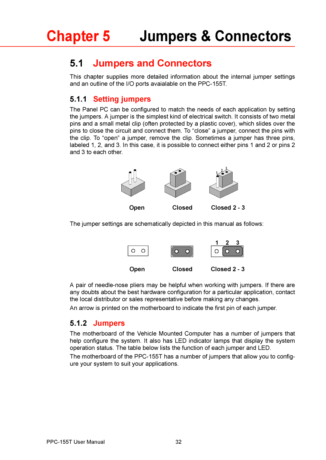
The Panel PC can be configured to match the needs of each application by setting the jumpers. A jumper is the simplest kind of electrical switch. It consists of two metal pins and a small metal clip (often protected by a plastic cover), which slides over the pins to close the circuit and connect them. To “close” a jumper, connect the pins with the clip. To “open” a jumper, remove the clip. Sometimes a jumper has three pins, labeled 1, 2, and 3. In this case, it is possible to connect either pins 1 and 2 or pins 2 and 3 to each other.
Open | Closed | Closed 2 - 3 |
The jumper settings are schematically depicted in this manual as follows:
Open | Closed | Closed 2 - 3 |
A pair of
An arrow is printed on the motherboard to indicate the first pin of each jumper.
5.1.2Jumpers
The motherboard of the Vehicle Mounted Computer has a number of jumpers that help configure the system. It also has LED indicator lamps that display the system operation status. The table below lists the function of each jumper and LED.
The motherboard of the
32 |
