Manuals
/
Advantech
/
Computer Equipment
/
Personal Computer
Advantech
PPC-155T
user manual
Jumper and Connector Locations
Models:
PPC-155T
1
46
68
68
Download
68 pages
13.42 Kb
43
44
45
46
47
48
49
50
Specs
Install
Warranty
Dimension
System Setup
Jumpers and Connectors
Appendix a Disassembly
Setting jumpers
Safety
Using the Panel PC
Page 46
Image 46
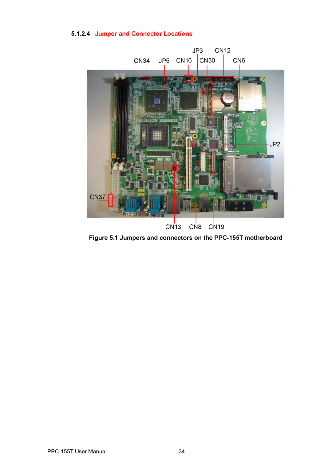
5.1.2.4
Jumper and Connector Locations
JP3 CN12
CN34 JP5 CN16 CN30
CN6
JP2
CN37
CN13 CN8 CN19
Figure 5.1 Jumpers and connectors on the
PPC-155T
motherboard
PPC-155T
User Manual
34
Page 45
Page 47
Page 46
Image 46
Page 45
Page 47
Contents
PPC-155T
Copyright Acknowledgements
Product Warranty 2 years
Declaration of Conformity
Technical Support and Assistance
FCC Class B
Document Feedback
Packing List
Additional Information and Assistance
Contact information
Safety Instructions
Wichtige Sicherheishinweise
Safety Precaution Static Electricity
Page
Using the Panel PC
Chapter
Appendix a
Appendix B
Chapter
General Information
Specifications
Introduction
General Information
Certifications
Dimensions
Dimensions of PPC-155T
Page
System Setup
System Setup
Quick Tour of the Panel PC
System Setup
Running the Bios Setup Program
Installation Procedures
Preparing for First-time Use
Installing System Software
Installing the Drivers
Page
Using the Panel PC
Using the Panel PC
CD-ROM Drive optional
Pcmcia
PS/2 Mouse and Keyboard
PCI Bus Expansion
PCI bus expansion
VGA Port
Serial COM Ports
USB Ports
Ethernet
Audio Interface
Front Bezel LED and Light Sensor
Touchscreen Optional
Page
Hardware Installation
Jumpers and Connectors
Hardware Installation
Disassembling the Panel PC
Hardware Installation
Installing the 2.5 Hard Disk Drive
PPC without the Rear Cover
Plugging in the Eide cable
Installing the Central Processing Unit CPU
Placing the CPU in the socket
Tightening the screws on the CPU
11 Fastening the CPU module to the motherboard
Installing the DDR Sdram Memory Module
12 Placing the memory module in the Dimm
Page
Jumpers Connectors
Jumpers & Connectors
Setting jumpers
Jumpers & Connectors
Jumper and Connector Locations
Connectors
Page
Driver Installation
Driver Installation
Driver Installation
Updating Driver Searching on the Advantech Website
Appendix a
Appendix a Disassembly
Disassembly Procedure
Appendix a Disassembly
Figure A.4 The PPC without the rear cover
Figure A.6 Unfastening the middle plate
Figure A.8 Unfastening the HDD module
Figure A.10 Disconnecting the HDD cable
Figure A.12 Loosening the screws on the CD-ROM module
Figure A.14 Removing the fixed brace
Figure A.16 Removing the CD-ROM / Pcmcia slot cover
Figure A.18 Disconnecting the CD-ROM connector
Figure A.20 Unfastening the CPU socket
Figure A.22 Removing the Sdram module
Page
Appendix B
Figure B.1 PCI Card Dimensional Limits
Appendix B PCI Card Size Limits
Top
Page
Image
Contents