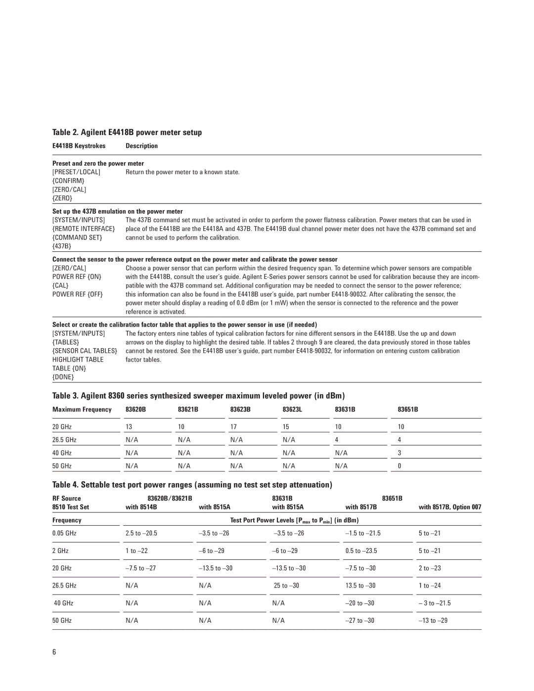
Table 2. Agilent E4418B power meter setup
E4418B Keystrokes | Description |
| |
Preset and zero the power meter | |
[PRESET/LOCAL] | Return the power meter to a known state. |
{CONFIRM} |
|
[ZERO/CAL] |
|
{ZERO} |
|
| |
Set up the 437B emulation on the power meter | |
[SYSTEM/INPUTS] | The 437B command set must be activated in order to perform the power flatness calibration. Power meters that can be used in |
{REMOTE INTERFACE} | place of the E4418B are the E4418A and 437B. The E4419B dual channel power meter does not have the 437B command set and |
{COMMAND SET} | cannot be used to perform the calibration. |
{437B} |
|
| |
Connect the sensor to the power reference output on the power meter and calibrate the power sensor | |
[ZERO/CAL] | Choose a power sensor that can perform within the desired frequency span. To determine which power sensors are compatible |
POWER REF {ON} | with the E4418B, consult the user’s guide. Agilent |
{CAL} | patible with the 437B command set. Additional configuration may be needed to connect the sensor to the power reference; |
POWER REF {OFF} | this information can also be found in the E4418B user’s guide, part number |
| power meter should display a reading of 0.0 dBm (or 1 mW) when the sensor is connected to the reference and the power |
| reference is activated. |
|
|
Select or create the calibration factor table that applies to the power sensor in use (if needed)
[SYSTEM/INPUTS] | The factory enters nine tables of typical calibration factors for nine different sensors in the E4418B. Use the up and down |
{TABLES} | arrows on the display to highlight the desired table. If tables 2 through 9 are cleared, the data previously stored in those tables |
{SENSOR CAL TABLES} | cannot be restored. See the E4418B user’s guide, part number |
HIGHLIGHT TABLE | factor tables. |
TABLE {ON} |
|
{DONE} |
|
|
|
Table 3. Agilent 8360 series synthesized sweeper maximum leveled power (in dBm)
Maximum Frequency | 83620B | 83621B | 83623B | 83623L | 83631B | 83651B |
|
|
|
|
|
|
|
20 GHz | 13 | 10 | 17 | 15 | 10 | 10 |
|
|
|
|
|
|
|
26.5 GHz | N/A | N/A | N/A | N/A | 4 | 4 |
|
|
|
|
|
|
|
40 GHz | N/A | N/A | N/A | N/A | N/A | 3 |
|
|
|
|
|
|
|
50 GHz | N/A | N/A | N/A | N/A | N/A | 0 |
|
|
|
|
|
|
|
Table 4. Settable test port power ranges (assuming no test set step attenuation)
RF Source | 83620B/83621B |
| 83631B |
| 83651B |
8510 Test Set | with 8514B | with 8515A | with 8515A | with 8517B | with 8517B, Option 007 |
|
|
|
| ||
Frequency |
| Test Port Power Levels [Pmax to Pmin] (in dBm) |
| ||
0.05 GHz | 2.5 to | 5 to | |||
|
|
|
|
|
|
2 GHz | 1 to | 0.5 to | 5 to | ||
|
|
|
|
|
|
20 GHz | 2 to | ||||
|
|
|
|
|
|
26.5 GHz | N/A | N/A | 25 to | 13.5 to | 1 to |
|
|
|
|
|
|
40 GHz | N/A | N/A | N/A | – 3 to | |
|
|
|
|
|
|
50 GHz | N/A | N/A | N/A | ||
|
|
|
|
|
|
6