Flatness-Correction Operation
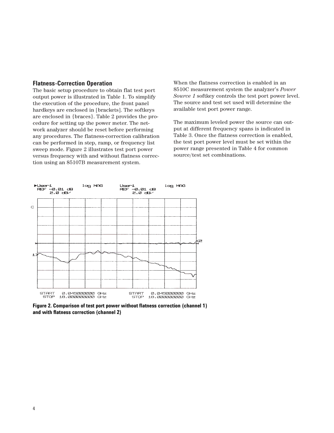
The basic setup procedure to obtain flat test port output power is illustrated in Table 1. To simplify the execution of the procedure, the front panel hardkeys are enclosed in [brackets]. The softkeys are enclosed in {braces}. Table 2 provides the pro- cedure for setting up the power meter. The net- work analyzer should be reset before performing any procedures. The
When the flatness correction is enabled in an 8510C measurement system the analyzer’s Power Source 1 softkey controls the test port power level. The source and test set used will determine the available test port power range.
The maximum leveled power the source can out- put at different frequency spans is indicated in Table 3. Once the flatness correction is enabled, the test port power level must be set within the power range presented in Table 4 for common source/test set combinations.
Figure 2. Comparison of test port power without flatness correction (channel 1) and with flatness correction (channel 2)
4