Using test port 1 calibrations on test port 2
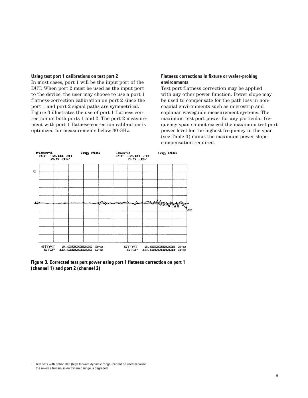
In most cases, port 1 will be the input port of the DUT. When port 2 must be used as the input port to the device, the user may choose to use a port 1
Flatness corrections in fixture or
Test port flatness correction may be applied with any other power function. Power slope may be used to compensate for the path loss in non- coaxial environments such as microstrip and coplanar waveguide measurement systems. The maximum test port power for any particular fre- quency span cannot exceed the maximum test port power level for the highest frequency in the span (see Table 3) minus the maximum power slope compensation required.
Figure 3. Corrected test port power using port 1 flatness correction on port 1 (channel 1) and port 2 (channel 2)
1.Test sets with option 003 (high forward dynamic range) cannot be used because the reverse transmission dynamic range is degraded.
9